• The move to the new server is done. There are some software and database maintenance updates in process. This has us passing the hat around to help out. We appreciate any donations. Seriously, even a dollar helps. The payment page may be found here - https://www.audiokarma.org/support.html

Acurus A250 and starground

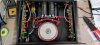
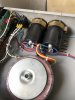
Halo, I’m still working on my A250 doing slow progress, I’m just gathering the last pieces of resistors to take it apart to change all resistors to Vishay RN60D, film caps to Wima MKP10, and Nichicon electrolitycs with Black Gate N on signal. The amp is playing all the time with my Thiel CS6. Thiels are very hard load. My bias is quite low around 4mV on emiters and yet in these hot days when I play loud it gets so hot that I can hardly touch it. I plan to put the pcbs apart and resolder all the resistors and capacitors at one time once I have everything.

I have a chance to get A200 in untouched condition and also A200x3. How would you describe the diffrance in A250 vs A200 sonically and as potential to mod. And also what would be the gain of buying A200x3? More place inside to maybe do a true dual mono with two transformers? Also can someone point out how exactly the Aragon 8008 differ from A200/250. There is some servo allowing skipping the input cap correct? All in all these are great amps to play with. Thanks in advance!

Will post the pictures once I make the progress with my A250.
 
Halo, I’m still working on my A250 doing slow progress, I’m just gathering the last pieces of resistors to take it apart to change all resistors to Vishay RN60D, film caps to Wima MKP10, and Nichicon electrolitycs with Black Gate N on signal. The amp is playing all the time with my Thiel CS6. Thiels are very hard load. My bias is quite low around 4mV on emiters and yet in these hot days when I play loud it gets so hot that I can hardly touch it. I plan to put the pcbs apart and resolder all the resistors and capacitors at one time once I have everything.

I have a chance to get A200 in untouched condition and also A200x3. How would you describe the diffrance in A250 vs A200 sonically and as potential to mod. And also what would be the gain of buying A200x3? More place inside to maybe do a true dual mono with two transformers? Also can someone point out how exactly the Aragon 8008 differ from A200/250. There is some servo allowing skipping the input cap correct? All in all these are great amps to play with. Thanks in advance!

Will post the pictures once I make the progress with my A250.
Ok I'll try...
If you have the chance to get an A200, I suggest you do so and sell your A250 before you start messing around with a soldering iron. The A200 sounds much better then the A250 out of the box in stock condition. I suspect that with decoupling caps added and RN60D + new caps + PSU, this thing WILL kill my own fully modded A250. The layout of the A200 is also better, so left/right channel is much more in harmony.
Looking at the Aragon 8008, it has DC-servo, no inputcap as Acurus. Also 12 Toshiba powertransistors pr channel instead of 8, true dualmono ect.....
I've read that a fully modded A200 should sound better then the Aragon 4004mkll..... I don't know if this is true to real life, but I'll bet it comes pretty close.
@mondialfan modded an A200, and maby he can tell more about the sound?

Regards
 
Last edited:
@zg3 if you decide to go with 4 e-caps in the PSU, I've just received a batch of lazercut groundplates for this mod. It will work in both A200 and A250. Send a PM if this becomes a reality and you want one.
IMG_20200820_160040.jpg
IMG_20200601_155524.jpg
 
Last edited:
Many thanks for your input. Why do you think there is the diffrance A200 vs A250? Schematics is the same, lower voltage rails and smaller ps caps and probably smaller transformer. Mainly layout? Also what is your thought on A200x3?

Thanks for the offer. On A250 I already put 2x36000uF Kemet and I’m more than happy with them. But I may want to get one or two for the future mods (looks great on yiur photos).
 

Attachments

  • 8A53E163-0609-4153-B173-BD7141A3992A.jpeg
    8A53E163-0609-4153-B173-BD7141A3992A.jpeg
    90.8 KB · Views: 14
  • 092179DE-2307-453C-99EF-71074A850205.jpeg
    092179DE-2307-453C-99EF-71074A850205.jpeg
    90.7 KB · Views: 14
  • 0532F5CD-5FDE-4933-A4AE-C63794ECB1D5.jpeg
    0532F5CD-5FDE-4933-A4AE-C63794ECB1D5.jpeg
    91.9 KB · Views: 14
Many thanks for your input. Why do you think there is the diffrance A200 vs A250? Schematics is the same, lower voltage rails and smaller ps caps and probably smaller transformer. Mainly layout? Also what is your thought on A200x3?

Thanks for the offer. On A250 I already put 2x36000uF Kemet and I’m more than happy with them. But I may want to get one or two for the future mods (looks great on yiur photos).
Those are good caps :)
The A200 just has a better circuit layout. I'll guess after some trail and error with the A250, Mondial finally fixed these issues in the A200. It's described a couple of pages earlier in this thread

Regards
 
Finally got my A200 disassembled for an inspection regarding the duallayer PCB. First thing I noticed was the wide layout footprint for the TO-92's. It does really make layout much easier then the standard triangled shape for a small signal transistor and I've corrected this in my own "tryout PCB drawing", especially at the diff-section this helps alot..
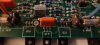
-One thing though: there is a marked GND between the two unused decoupling caps C16/17 ( see picture). I thought the ground from these caps would be incorporated in the PCB'c copper to a suitable position on the circuit.. Anybody knows if this was intended to connect by wired the the common GND out at speaker minus or local connection at starground?
IMG_20200907_202750.jpg

Best regards
 
Last edited:
IMG_20200917_182921.jpg
Ready for assembly... This one and a few other amps I have in right now has been on a loooooong journey, that said I have stopped for further incoming amps for a month or two until the amps that are in right now are finished.. Since my spare time has been squeezed to absolute minimal with my daily job pushing boundaries with an extreme amount of hours per week, the amps has been stalled :oops:! Luckily all owners has additional amps to play their music while I build/rebuild and they took it quite well when they received the message about delivery. Finally I have the time to once again continue where I left and finish some projects :)

Regards
 
Building this one..... I think it's the oldest one I've seen. The voltage regulator had to be moved to make room for the extra caps and bridge. All AC wires had to be redone as a result, also the xformer connections had to be cut to fit and resoldered.
Usually I clean everything as close to perfection as possible, but this one has seen so many year's with full load of nicotine that it's impossible. It's under the foil in the xformer and discoloured all of the old heatshrink that's left in this amp:(
IMG_20201019_212035_Bokeh.jpg

Regards
 
That's a very nasty amp Knielsen. I've had a few that were loaded with cigarette smoke residue but none of them were in that poor of a condition. Maybe that one was in a bar/pub at some point in its life.
 
These just arrived (ACROL HS100 8R) so I can start make some squarewaves ect:)... Many asked for some "A250-measurements" under full load, but for me it's more how the amp behave within. Anyway, these dummyloads are capable of 200w@8Ω/400w@4Ω mounted on a heatsink, so it's a start but not enough for a +300w@8Ω measurement yet..
I'm not sure if I should have bought the "n-version" (non-inductive), so I were on the edge to put them for sale again when I discovered my potential mistake when adding these to the basket, but think I'll start here first;)
IMG_20201019_165835_Bokeh.jpg
 
Last edited:
The inductance is probably negligible. I bought a bunch of old ceramic coated ohmite resistors from Apex Jr. to build mine. Its been a long time since I built the dummy load but if I remember correctly I used a bunch of 50ohm resistors in parallel to create a very high powered 8 ohm/4 ohm dummy load. The nice thing about inductance is that when its in parallel its reduced just like parallel resistance. So when you gang up a set of 4 resistors to make a higher power single 8 ohm resistor you'll have the equivalent inductance of a single resistor.

You have enough resistors there to configure 400W@8ohms stereo. You have 4 pairs, each paralleled pair is 4ohms/200W so two pairs in series is 8ohm/400W. If you parallel the two 8ohm/400W pairs you get a single 4 ohm/800W resistor but you can only test one channel at a time into 4ohms. I like to do two channel tests because it shows the limits of the power supply and simultaneously running two channels at full power is actually easier on the individual channels because of the power supply sag when the two channels are fully loaded. So less energy is available to each channel when both channels are being driven into a load as opposed to a single channel test which is capable of using all of the power supply's energy.

The resistors you're using can probably handle much higher loads than 100W for a few seconds especially if they are tied to a heatsink. Wirewound resistors are usually a bit more tolerant to overload conditions for brief periods than say a metal film resistor. This means they will work well for automated test systems that only hold the amp at full power for a very short time, i.e. Quant Asylum QA401, Audio Precision, etc. If you're manually testing then you'll have to be careful not to exceed the rating for more than a second or two. Also remember that square waves give off more energy than comparable voltage sine waves so its easy to over load your dummy load resistors if you forget about this.
 
The inductance is probably negligible. I bought a bunch of old ceramic coated ohmite resistors from Apex Jr. to build mine. Its been a long time since I built the dummy load but if I remember correctly I used a bunch of 50ohm resistors in parallel to create a very high powered 8 ohm/4 ohm dummy load. The nice thing about inductance is that when its in parallel its reduced just like parallel resistance. So when you gang up a set of 4 resistors to make a higher power single 8 ohm resistor you'll have the equivalent inductance of a single resistor.

You have enough resistors there to configure 400W@8ohms stereo. You have 4 pairs, each paralleled pair is 4ohms/200W so two pairs in series is 8ohm/400W. If you parallel the two 8ohm/400W pairs you get a single 4 ohm/800W resistor but you can only test one channel at a time into 4ohms. I like to do two channel tests because it shows the limits of the power supply and simultaneously running two channels at full power is actually easier on the individual channels because of the power supply sag when the two channels are fully loaded. So less energy is available to each channel when both channels are being driven into a load as opposed to a single channel test which is capable of using all of the power supply's energy.

The resistors you're using can probably handle much higher loads than 100W for a few seconds especially if they are tied to a heatsink. Wirewound resistors are usually a bit more tolerant to overload conditions for brief periods than say a metal film resistor. This means they will work well for automated test systems that only hold the amp at full power for a very short time, i.e. Quant Asylum QA401, Audio Precision, etc. If you're manually testing then you'll have to be careful not to exceed the rating for more than a second or two. Also remember that square waves give off more energy than comparable voltage sine waves so its easy to over load your dummy load resistors if you forget about this.
Great response. I'll keep in mind that squarewaves should be performed with load and in the range of 3-5vpp. Still remember my own amp with 10vpp and no load!! Some funny curves came out of this test:D, and a zobelnetwork that started to show the pressure:eek::)

Best regards
 
Done!! By far the hardest build I've done, with new AC-plug, complete new wire harness (minus the xformer, only reduced the wires here about 3" and resoldered), moved voltage regulator, new inputsignal wires ect ect ect..... And the cleaning not to mention. Almost to much and a loooooong journey with many processes, and a set date for delivery (next weekend)..
Did a quick powerup and everything ok. And sorry for the mess at the table, it's getting late here but wanted this finished before bedtime, so the internal wires hasn't been aligned properly yet, and the internal chassic hasn't been cleaned before this photo was taken... Continue tomorrow with my new scope and signalgenerator, this is gonna be fun!:)
:banana:
IMG_20201023_234804.jpg
 
Last edited:
364W@8Ω before clipping, one channel driven. Haven't made the second dummyload yet ;)

Also the 5Vpp is dead straight, no ringing at all
IMG_20201024_133651.jpg
IMG_20201024_142620.jpg

I've should have bought this equipment years ago

Best regards
 
The triangled curve: does it provomide any useful data on the behaviour of an amplifier??

So far I've been using sine and squarewaves. Tried the triangle in my A200 for test, but think the zobel didn't like this, the resistor now got some black spots that I didn't see before, and do not measure that well in resistance. The trianglewave were performed at very low Vpp, under 3vpp if I remember correctly.
I've seen others use triangle to determine a flaw in the driver-transistors, but how does an Acurus behave to this signal.

Maby the zobel were already damaged, but I think the triangle with a 8Ω load did this?!??

Best regards
 
Last edited:
Back
Top Bottom