• The move to the new server is done. There are some software and database maintenance updates in process. This has us passing the hat around to help out. We appreciate any donations. Seriously, even a dollar helps. The payment page may be found here - https://www.audiokarma.org/support.html

Acurus A250 and starground

Nice with a closeup Mondiallfan although I'm finished for now :) .. next time (my other A250) I place my postmod caps like your pic shows, would have been alot easier... And much less wire to attach..

I see you only changed R1 and R2. Are these the most important on the circuit?

Also, the power transistors.. in both my A250's there are 4 green/4 black.. are the once we are looking at new?? Or did Mondial source their transistors from different companies since they are all black (maybe a noob question) :) ?

R7 & 14 are undersized and tend to get brown over time, replace those with higher wattage or use RN-60's.

The early Toshiba transistors were green & black. Later production parts switched to all black. That's one indication of the vintage of your boards, early 90's or mid-90's.
 
Thank you Mondialfan
To drill the 4 holes for the film and e-cap 2 of them should be right next to the DC rail trace then solder one side of the two caps to the DC rail trace on the soldering side of the board and attach a wire to the other side of the two caps to board ground. Is it right?

Yep, you got it!
 
Jdk07 please share your mods if possible so we can we see them :)
I did not do any mod yet just learned about the post fuse cap from reading your amp project so i want to try this mod first. if i would do any major mod in the future when i m learned more about amp mod i would share for sure. Thank you
 
The ECWF you recommended to use for this e-cap which lead side should attach to DC rail trace? thank you
If I understand your question correctly: the Panasonic ECWF(a) are bipolar capacitors. Just attach both legs from the ECWF to the e-cap where it is placed at the board (the small Panasonic cap only funktions as a little helper across the bigger e-cap). The legs from the e-cap goes to your rail somewere after the fuse and to ground (plus some added wire if needed) :)
 
If I understand your question correctly: the Panasonic ECWF(a) are bipolar capacitors. Just attach both legs from the ECWF to the e-cap where it is placed at the board (the small Panasonic cap only funktions as a little helper across the bigger e-cap). The legs from the e-cap goes to your rail somewere after the fuse and to ground (plus some added wire if needed) :)
Thank you i saw a video showing bipolar cap has the shield end and it should be place in the circuit accordingly
 
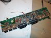
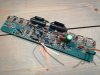
IMG_20180311_003319-1984x1488.jpg IMG_20180311_002319_BURST001_COVER-1984x1488.jpg My first tryout... Not how I ended up, but it gives an idea how it also could be done.. both e-cap and bypass filmcap are mounted after each fuse and then connect to form a single wire to ground. I discarded this method (shown on the picture) due to the size of the Jantzen Alumen filmcaps. The rest is in this thread.
 
View attachment 1461067 View attachment 1461063 My first tryout... Not how I ended up, but it gives an idea how it also could be done.. both e-cap and bypass filmcap are mounted after each fuse and then connect to form a single wire to ground. I discarded this method (shown on the picture) due to the size of the Jantzen Alumen filmcaps. The rest is in this thread.
Did you try this method on your other acurus to see how it would sound
 
Did you try this method on your other acurus to see how it would sound
No..

It was my idea to form a new groundtrace to a new starground, also from the postfusecaps. But without equipment to measure (regarding the size of the caps and potential groundloops) I didn't continue. Mondialfan's mod works floorless as it is, I can hear now :)

But I did change the remaining grounds to one commen ground, a starground. I tested this on my other A250, while building this one. I remember the first thing that came to my mind when first listened to the new ground in my "test amp A250": better instrument separation! - Anyways, that's what I think.. ;)
Optimum ground connection.jpg

The idea behind my grounds is to separate the noise for the power grounds from the sensitive input grounds, therefore a new input ground trace was made also.

This is the man who helped me with the grounds: http://kajmogensen.dk/Powercord_UK.html
 
Last edited:
No..

It was my idea to form a new groundtrace to a new starground, also from the postfusecaps. But without equipment to measure (regarding the size of the caps and potential groundloops) I didn't continue. Mondialfan's mod works floorless as it is, I can hear now :)

But I did change the remaining grounds to one commen ground, a starground. I tested this on my other A250, while building this one. I remember the first thing that came to my mind when first listened to the new ground in my "test amp A250": better instrument separation! - Anyways, that's what I think.. ;)
View attachment 1461145

The idea behind my grounds is to separate the noise for the power grounds from the sensitive input grounds, therefore a new input ground trace was made also.

This is the man who helped me with the grounds: http://kajmogensen.dk/Kajsklumme.html
A danish page (sorry :) )... His own DIY on display
I should have said "these caps " not "this method" on your other amp. I will try your starground someday
 
(1) go with 100uf/100v Elna Silmic ll... They are good for this application. Use a small film cap for bypass with at voltage rating from 200v and up.. I use Panasonic ECWF(a) 1uf/250v
(2) yes
(3) yes

;)
I have some 220uf/25v Elna Silmic II, do you think it could work for this application or it is too high uf and voltage is too low
 
I have some 220uf/25v Elna Silmic II, do you think it could work for this application or it is too high uf and voltage is too low
It's to much. The function of the fuse will be bypassed if something is wrong. 100uf is the maximum if I would use to keep the safety of the fuses! :) and it has to be 100 volts also.
 
It's to much. The function of the fuse will be bypassed if something is wrong. 100uf is the maximum if I would use to keep the safety of the fuses! :) and it has to be 100 volts also.
Thank you I bought them to replace c7 and learned that c7 uses bipolar cap so they are just sitting there so I thought maybe I could find some use for them
 
Thank you I bought them to replace c7 and learned that c7 uses bipolar cap so they are just sitting there so I thought maybe I could find some use for them
Go with Nichicon Muse ES (bipolar cap) for C7... I think mine is 220uf/50v at this location.
25v should be enough according to the schematic though...
 
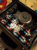
IMG_20190410_212427-665x887.jpg
Small update:
I've added 1uf/250v Panasonic ECWF(a) in parallel to the PSU caps, 8 in total (next to the grey resistors).. It has improved the upper frequency. I got no measurements supporting this.
 
Is there any reason why Acurus added R35-38 on the A200 series? These are not found in the A150/250 amplifiers I've looked at..

Regards
 
Back
Top Bottom