• The move to the new server is done. There are some software and database maintenance updates in process. This has us passing the hat around to help out. We appreciate any donations. Seriously, even a dollar helps. The payment page may be found here - https://www.audiokarma.org/support.html

Acurus A250 and starground

Is there any reason why Acurus added R35-38 on the A200 series? These are not found in the A150/250 amplifiers I've looked at..

Regards

These resistors are for emitter degeneration. Degeneration can help to force current sharing through the diff pair and can help to bring down gain.

The early Mondial amps used the NEC C1598/A798 which were matched transistor pairs on the same silicon. Unfortunately the NEC's used a common emitter pin so they were a 5 pin device. It wasn't possible to degenerate them. Later devices including the A200 used the Toshiba C3381/A1349 matched transistor pairs, these used separate emitter outputs for each transistor so degeneration was possible.

FYI, the A200 schematic floating around on the net is wrong. It shows the NEC devices in the A200 when the later Toshiba matched input transistor pairs were actually used. This was an artifact of someone using the old A250 schematic and trying to draw in the changes. I drew up a proper schematic of the A200 to use when I'm working on them. I'll dig around and see if I can find it.
 
Very interesting. So I shouldn't be able to try this on my A250 if I understand :)

If you find the schematic, you may send one.

Thanks
 
Very interesting. So I shouldn't be able to try this on my A250 if I understand :)

That's correct its not possible to do degenerate the input pairs in an A250.

I uploaded my version of the A200 & A200X3 2nd gen schematics to HIFIEngine. I also uploaded my cleaned up and updated version of the A250 & A200X3 1st Gen so hopefully they'll be available in the next few days to anyone that might need them.
 
That's correct its not possible to do degenerate the input pairs in an A250.

I uploaded my version of the A200 & A200X3 2nd gen schematics to HIFIEngine. I also uploaded my cleaned up and updated version of the A250 & A200X3 1st Gen so hopefully they'll be available in the next few days to anyone that might need them.
Thanks

I'll be checking this one for sure! :)
 
That's correct its not possible to do degenerate the input pairs in an A250.

I uploaded my version of the A200 & A200X3 2nd gen schematics to HIFIEngine. I also uploaded my cleaned up and updated version of the A250 & A200X3 1st Gen so hopefully they'll be available in the next few days to anyone that might need them.
The 12v +/- indication on the A200 gen2 schematic.. what is this? A trigger?

Btw I've opened a new thread regarding P10 rebuild: https://audiokarma.org/forums/index.php?threads/acurus-p10-phono-stage-mod-rebuild.869125/ :)
 
The 12v +/- indication on the A200 gen2 schematic.. what is this? A trigger?

The +/- 12V indication is a leftover from the Aragon 8008 schematic that I modified to turn into the A200. These voltage points are where the front end XLR diff input circuitry gets its power from on the 8008bb. For the A200 these could just be considered test points.

I'll post something on your P10 thread in the next day or so. Got a lot going on right now. There's not a big difference between a 47k & P10, virtually identical with an external PS.
 
The +/- 12V indication is a leftover from the Aragon 8008 schematic that I modified to turn into the A200. These voltage points are where the front end XLR diff input circuitry gets its power from on the 8008bb. For the A200 these could just be considered test points.

I'll post something on your P10 thread in the next day or so. Got a lot going on right now. There's not a big difference between a 47k & P10, virtually identical with an external PS.
Thanks.. I'm hoping for your .02¢ on the P10.. not much information available:)

Regards. Good dag
 
I've been wondering why I could hear a different and more precise bass/mid when I removed my bleeder resistors from the PSU on my A250.....?? Not much but enough to question it... and why the 4x bigger power supply only lasted 30sec after turning off the amp?

The answer: I made a series rookie mistake, and paralleled two 12k on each of the 8 caps in PSU.
My goal was 6k bleeder, but don't know where my thoughts were since I didn't consider that each cap with bleeder form ONE BIG resistor!:confused: So eighth 12K on each channel in parallel = 1.50k not 6k:boring:

Removing the bleeder's and the amp play's for almost 2 minutes before noticeable noise occurre after turned off, played at reasonable listening level:)

-We all make that one stupid mistake now and then. Just wanted to share mine:rflmao:
 
Last edited:
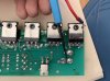
Many of the A250 I've opened seems to be burned (or brown'ish) around Q5/6/7 & Q12/13/14, but the amplifier seams to play just fine. Typically R4 is also brown when the marks are present at the transistors.
Why is that??

Regards
 
Many of the A250 I've opened seems to be burned (or brown'ish) around Q5/6/7 & Q12/13/14, but the amplifier seams to play just fine. Typically R4 is also brown when the marks are present at the transistors.
Why is that??

Regards
I suspect R4 to be underrated, leading to the overload..? :)
 
Well talkin to myself, I've found the answer, I think.
The transistors at lokation mentioned above are working in class A at all time, with heat as a side effect of course:)

Regards
 
Last edited:
Sorry I've been out of town on vacation for the past week.

R4 showing browning is unrelated to Q6/7 & Q13/14 browning the surrounding board. You'll notice that those transistors are running in parallel the reason for this is due to the loading on them. They also have a lot of idle dissipation so they get very hot. The big brother Aragon's used a single TO-220 heatsinked transistor in this location which is a better solution.

R4 is the current limiter for the voltage reference diodes on the front end differential LTP's and with 90V DC rails its only dissipating approx 160mW so its fine. I've never seen one getting brown so I'm not sure why you would be seeing this unless someone incorrectly adjusted the AC mains voltage tap mechanism in the rear fuse holder which could cause an overvoltage situation.

I have seen R7/R14 turning brown and these are underrated for their task. They are 1/4W rated resistors and are dissipating approx 275mW each with 90V rails. I usually install a Dale RN60 (milspec 1/4W which is really a 1/2W) or a 1W panasonic in these locations due to the high dissipation they see.
 
R4 is the current limiter for the voltage reference diodes on the front end differential LTP's and with 90V DC rails its only dissipating approx 160mW so its fine. I've never seen one getting brown so I'm not sure why you would be seeing this unless someone incorrectly adjusted the AC mains voltage tap mechanism in the rear fuse holder which could cause an overvoltage situation.

Hope it was a good vacation ;)

One amp the voltage mechanism is set faulty(if you are in Denmark) at 220vac, not 240vac. Since we have 230vac it gives some ekstra voltage to the rails, instead of 85vdc, it will roughly be around 92vdc at the rails. But the other amp also with a brown R4 is Gen2 (black power transistors, wima throughout ect..) with 230v support at the AC.. it should be ~85vdc compared to to previous models I've measured. So I have to look into that..
I haven't gotten into details with the amplifiers yet, only opened the lids for a quick inspection. -My wife been out with the girls this weekend, so had to take care of the kids. Not the best time to measure live powered electronics, when there really is not that much time to focus :D

Regards

Edit: my own A250 is running approx 91.5vdc if I remember correctly, no problems at all.
 
Last edited:
Im doing some similar preventative maintenance and mods to my 200x3 and I have a quick question about adding the supply line capacitors after the fuses. I plan to add the caps(47u/100v Nichicon Muse) on top of the board like MondialFan showed in his pic but I’m having a hard time figuring out the best spot on the bottom of the board to connect to ground? I was planning to solder on leg of the capacitor directly the V+ or V- fuse holder on the bottom of the board and run a piece of wire back to ground point shown in my pic. Is this correct? 947732B4-F619-47B4-8A6D-9DC190E7C354.jpeg
 
I was planning to solder on leg of the capacitor directly the V+ or V- fuse holder on the bottom of the board and run a piece of wire back to ground point shown in my pic. Is this correct? View attachment 1624579
This is the way I did this mod as you are planning.
You could select other connections then directly at fuse V+/- if this fits your project better, as long as it is directly on the rails after the fuse.

Regards
 
As long as the ground wire you add goes back to the black wire (Gnd) connected to the neg speaker post you'll be fine. I usually use 100uF/100V caps but 47uF will be fine.
 
Back
Top Bottom