• Please note that Audiokarma will be offline briefly for updates early on Monday morning, September 28th.

Add LED and Aux to Zenith K731

mcaddie7

Active Member
Hi all,

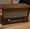
Title says it all. Found an old Zenith radio that looks pretty good. Replaced the caps and it’s singing!

However I have three issues:

1) The FM, AM, FM AmC switch is kinda bad. Any tips on replacing, / could I wire it just to FM?

2) I’d like to add a led to the tuning dial that follows the dial. Could I tap into something and scale down the voltage with a resistor?

3) if possible, could I also add an aux that takes priority? Meaning that the FM /AM plays but if something is plugged into the aux, it uses that?

Thanks!
 

Attachments

  • IMG_3739.jpeg
    IMG_3739.jpeg
    109.1 KB · Views: 18
Register to hide this ad
Are you saying you want to light up the tuning dial so you can see it? Or are you wanting a power on indicator?

Concerning an Aux input, I think you could add an RCA input jack on the back but selecting it as the signal source input would require wiring it to a selector switch of some kind. Ideally you’d want to be able to select AM, FM, or Aux from the front panel. So replacing the wobbly selector with a new one that allowed you to select the new input seems the most straightforward.

You could get fancy and add a blue tooth input board so that you could connect your phone to it. Depending on the board, it might have a way to auto switch to the connected blue tooth device. All of this wouldn’t be too hard but you’d need to power the board somehow with an external power supply that you’d need to build and install in that chassis somewhere.
 
I’d like to add an led to the dial string. I’d like to just mount it to the white bar that moves. I figured if I can find a DC voltage somewhere I can use a resistor to scale it down to 8V (rate of my spare LEDs), no?

As far as the switch, I probably should replace it as the current one just doesn’t feel all that good. Would you like a picture of it? I’ve never replaced a switch like that before and am unsure about requirements
 
Yeah that’s the idea on how to power an LED. Find a suitable power source like a 6 or 12 volt filament source, add a dropping resistor so you limit current to the LED. You can power it from an AC source or from a DC source. Diode polarity won’t matter with an AC source but if your eyes are sensitive you might notice a flicker since the LED will block current in one direction. If you use a 12v or 6V source start with a resistor size of say 1k and adjust accordingly for the brightness you want. If powering from 120V or anywhere in that range, start with a 100k resistor and adjust accordingly.
 
For the switch, some selector switches have a mode that turns on power too. Others simply select between various inputs. How does the selector switch operate in your unit? Also you need to know if it’s stereo (two channel) or mono. It looks like a slider switch from your picture.
 
To power an LED on a tube amp I use a small bridge rectifier on the 6.3V heater circuit with a 16V 330uf cap across the output, which boosts the voltage slightly and provides DC which eliminates flicker. Then use a 3-5K resistor or larger to limit current and tune the value to the brightness I want.
 
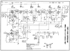
I have a suspicion this has no power transformer and no 6v heater supply, which is why I want to see a schematic.
 
I have powered a standard red LED from 120/240VAC with a 100k/0.25W resistor with no flicker or other issues. Works great.

Other color LED's may require the resistor value to be changed slightly. A lot of 120/240VAC panel mount switches use just a resistor and LED (previously neon bulbs and resistors) and there is never any flicker.
 
mmmhmm, as I suspected, no transformer.

stealing a little DC off the output tube cathode could be done. I might go for a "light pipe" sort of setup on the pointer. Instead of just mounting an LED there, make the pointer itself from a clear plastic rod and sand the front edge so it looks kind of frosted. Shine the light down though it, and it will light up the sanded surface. Loads of 70s tuners did it basically this way.

I might also consider neon or an orange LED that looks like neon. I think it would visually look more appropriate for the era of the unit than a red LED.


switch wise I think that would be what, 3P3T ? Mouser has 2 that might work, you'd have to check the dimensions and such though.


If its functional possible you can fix it. If its just gummy often a good shot of something like Faderlube or the CRC precision lube will get them working well again. The original grease gets petrified and then the detent ball doesn't do its job anymore.
 
Hi all thanks for the feedback. So I have a warm white LED labeled 6V that I tried using. I connected it to a tap somewhere I can't remember at this moment that had 6 V, and the other side to the chassis.

Oddly enough it doesn't seem to always light when powered on, so maybe a loose connection or a bad place to place it.

Some basic electronics questions but I always love learning from you all rather than AI generated answers :)

If have some ~60 and ~80V sources I could connect it to via tube terminals, would I not need a larger resistor, say 2W instead of a standard 1/4W due to the amount of voltage we are stepping down?

Either way when it does light it actually looks awful and shines through the plastic. I'm definitely going to try and make some sort of light tube to connect it to.


Now, as far as adding an Aux input, I think I want to remove the wires on the AM switch and use that. But have 0 idea where to wire the Aux input. I'm guessing somewhere in the amp circuitry itself, but am unsure where the L, R and ground should go as well as how to wire the AM part of the switch to achieve this. Any help would be great! I can always take a picture of the actual circuitry if need be.
 
Concern with an aux input is this doesn't really have proper isolation from the mains. It has one side of the power cord tied to chassis, which makes it quite dangerous to connect anything external to it. To do it safely you really want a 1:1 isolation transformer on either the power line or the aux input.

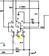
but if you're deleting AM, do this

1738933603631.png

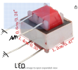
unhook the orange wire, connect the aux input between the highlighted terminal and ground. I'd use a transformer here to make it safe. Something like this will work


The orange lead is what provides screen current to the AM converter tube. Its what gets disconnected in FM mode anyway.

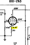
The only thing in here with 6v is this spot

1738933843928.png

this is DC, and there is approx 42ma of current available. Should be enough to light an LED but since its DC polarity matters. Get the LED backwards and it won't light. Also depending on the LED current it might be preferred to bump the cathode resistor value a smidge to keep the total current flow through the output tube the same.
 
Hi Gadget,

1738955633385.png

If I bought one of these, would this be the wiring for all four pins, with the other end of the LED at that 6VDC tube? In basic terms, how does using something like this make it "safer".

Thanks!

Going to order all this. In the meantime, buying stain this weekend to make the wood a bit darker to hid some of the water stains from past owners.
 
the transformer is for the aux input, not the LED. On the radio side, one lead to ground, the other to the switch.

On the other end, both go to your aux input jack. They never touch the ground of the radio. This keeps the aux input jack from having any direct connection to the radio, meaning whatever you plug in to the jack isn't connected directly to the power line.
 
Gadget has brought a very good point to this discussion, which is there is no mains isolation transformer on this unit. This means the chassis is a "hot" chassis design. With the audio isolation transformer approach discussed above, that means still a "hot" chassis, just that the aux input is now isolated from being able to see mains voltage on the chassis.

When you insert the mains plug into your wall outlet, there's a 50-50 chance the hot lead from the wall outlet connects to the chassis of the radio. Therefore, in that condition, if you touch the metal on the chassis, or anything metal connected to the metal of the chassis...zap! It will wake you up in a hurry. (I've had my share of being zapped like this).

A safer solution is to isolate the entire chassis. To do it, you could use one of these as a mains isolation transformer: https://www.antekinc.com/au-5455-500va-55v-ul-transformer/

This is quite a bit larger than the audio isolation transformer approach, and may not fit anywhere inside the unit. Nonetheless it is a much safer approach if you can somehow finagle it to fit. This approach is addressing the root issue of the hot chassis design.

One more point. Notice how the designers dealt with the hot chassis issue back in the day--notice they have conveniently covered up all metal exposure of the chassis or anything metal connected to the chassis with plastic or other insulating material, so when operating it, there was supposedly little chance of your fingers touching metal. Using a polarized two prong plug doesn't really address the issue either, since your house outlet could be unknowingly wired backwards.

If you choose not to address the hot chassis situation, I would say just be careful when operating it.... The first time this happened to me was when I was probably 7 or 8. My dad had a table FM radio that was a hot chassis design. The plastic power knob cracked and fell off but I thought I could still turn the radio on/off directly by just grabbing the metal shaft of the on/off knob and turning it.....zap! I survived but it taught me a big lesson.
 
the transformer is for the aux input, not the LED. On the radio side, one lead to ground, the other to the switch.

On the other end, both go to your aux input jack. They never touch the ground of the radio. This keeps the aux input jack from having any direct connection to the radio, meaning whatever you plug in to the jack isn't connected directly to the power line.
In terms of speakers, the parts came in today and I know the radio has mono speakers. So I just twist the red and white wires from the aux input together before soldering to the little transformer? I want both signal paths to get to the speaker
 
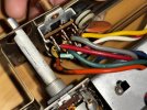
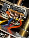
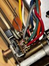
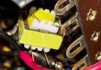
So I ran into an issue, you mentioneed I should remove the orange and add my Aux to pin 5. Pin 1-4 are wired the same but it appears on mine that pin 5 is blue, pin 7 is green I believe, and pin 8 is gray? Pin 12 appears to be ground and yellow per the schematic so that’s good.

Where would I put the aux and cut in this case?


Concern with an aux input is this doesn't really have proper isolation from the mains. It has one side of the power cord tied to chassis, which makes it quite dangerous to connect anything external to it. To do it safely you really want a 1:1 isolation transformer on either the power line or the aux input.

but if you're deleting AM, do this

View attachment 3420621

unhook the orange wire, connect the aux input between the highlighted terminal and ground. I'd use a transformer here to make it safe. Something like this will work


The orange lead is what provides screen current to the AM converter tube. Its what gets disconnected in FM mode anyway.

The only thing in here with 6v is this spot

View attachment 3420625

this is DC, and there is approx 42ma of current available. Should be enough to light an LED but since its DC polarity matters. Get the LED backwards and it won't light. Also depending on the LED current it might be preferred to bump the cathode resistor value a smidge to keep the total current flow through the output tube the same.


I also added the little transformer to ground in pin 4, but want to be extra sure where the other pins go.

Thanks for the help!

IMG_3867.jpegIMG_3866.jpegIMG_3868.jpegIMG_3864.jpeg
 
Back
Top Bottom