• The move to the new server is done. There are some software and database maintenance updates in process. This has us passing the hat around to help out. We appreciate any donations. Seriously, even a dollar helps. The payment page may be found here - https://www.audiokarma.org/support.html

Adjusting DC Offset on Technics sa 400

Theo A

Active Member
Hello all,
After getting a dead technics sa 400, I narrowed the problem down to a shorted power pack and replaced it. Low and behold, everything was working alright, but the dc offset is pretty high now. This is a relatively higher model in the technics line, are there pots to adjust the offset ?
 
Register to hide this ad
I see my mistake; they are not matched properly. How can I make sure I get a good match, in other words what do I test for because the one in right now is the correct model just not synced up with the other one
 
What's not matched properly? No adjustments in that model, you'll have to replace Q601 and Q602 with matched pairs, KSA992 seems to be the go to transistor for the input differential pair.
 
What's not matched properly? No adjustments in that model, you'll have to replace Q601 and Q602 with matched pairs, KSA992 seems to be the go to transistor for the input differential pair.
I replaced the left channel power pack, I guess that doesn’t have an impact on dc offset? I’ll find q601 and q602, is this the only way to adjust offset?
 
If working the power packs would not be my first choice for DC offset. Q601 and Q602 are dual transistors that have probably drifted apart electrically over the years assuming they were matched in the first place. You'll have to match up two pairs of KSA992s to replace the 2SA798s.
 
I replaced the left channel power pack, I guess that doesn’t have an impact on dc offset? I’ll find q601 and q602, is this the only way to adjust offset?
Maybe, maybe not. Or maybe it was off before. Who knows?

What is it now? Replacing the transistors is the simplest way.
 
It’s around 80 to 85...
Yep! That should be fixed. An hFE match should be ok. Lots of multimeters can do this, or buy one of the component checkers at auction. I love those things. Cheap, not very accurate, but gets you into the ballpark every time.
 
Yep! That should be fixed. An hFE match should be ok. Lots of multimeters can do this, or buy one of the component checkers at auction. I love those things. Cheap, not very accurate, but gets you into the ballpark every time.
Thanks, what keywords should I look for I am clueless on what to buy
 
First, do you have a multimeter? If so, does it have a transistor tester? I ask, because if you are going to be doing much of this work, a multimeter is a necessity. And buying one with a transistor test function might make the most sense, if you don’t already have a meter.

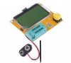
If you want a component tester, look search for electronic component tester. I have one something like this. As I said, I would not use it for precision work, but it’s worth the $15 to $20, and it will get your hFE much closer than 80mV.
27155374-572E-420A-9E01-84A0312E4D6D.jpeg
I added mini-grabber clips to mine. That’s a real improvement. They now sell ones with mini-grabbers.
 
Last edited:
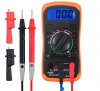
Here is a multimeter with transistor tester for $12 from a big online retailer.
D408EBD7-4877-492B-8F4D-B76D3B9F5F26.jpeg
$12! I have no idea how they can make, ship, sell and deliver that for $12. I’m sure it’s not protected and I’d blow it up within the week, but...$12! I spend that on coffee and baked goods for the wife and me.

Anyway, this online retailer also has the component checker. Which one to get depends on if you already have a meter.
 
I do have a
First, do you have a multimeter? If so, does it have a transistor tester? I ask, because if you are going to be doing much of this work, a multimeter is a necessity. And buying one with a transistor test function might make the most sense, if you don’t already have a meter.

If you want a component tester, look search for electronic component tester. I have one something like this. As I said, I would not use it for precision work, but it’s worth the $15 to $20, and it will get your hFE much closer than 80mV.
View attachment 2143668
I added mini-grabber clips to mine. That’s a real improvement. They now sell ones with mini-grabbers.
multimeter but no transistor tester. I’ll check this one out thank you
 
First, do you have a multimeter? If so, does it have a transistor tester? I ask, because if you are going to be doing much of this work, a multimeter is a necessity. And buying one with a transistor test function might make the most sense, if you don’t already have a meter.

If you want a component tester, look search for electronic component tester. I have one something like this. As I said, I would not use it for precision work, but it’s worth the $15 to $20, and it will get your hFE much closer than 80mV.
View attachment 2143668
I added mini-grabber clips to mine. That’s a real improvement. They now sell ones with mini-grabbers.
How did you connect up the mini grabbers to the device
 
Actuslly, I soldered them to the ZIF socket's solder pads, then tie-wrapped them to the board for strain relief.
That'll work too. :thumbsup: I use the ZIF socket so I can easily detach them when the wires break in the minigrabbers and need repaired. You do want to keep the leads short for better accuracy too. I got the one with the clear acrylic case so it has some protection, and contains the battery from flopping around.
 
If working the power packs would not be my first choice for DC offset. Q601 and Q602 are dual transistors that have probably drifted apart electrically over the years assuming they were matched in the first place. You'll have to match up two pairs of KSA992s to replace the 2SA798s.
I don’t know how to put in the correct Pinout, especially because the 798 transistors have 5 legs...
 
Look in the Service Manual to determine which legs are which on the 5-legged transistor. One of those legs is common to both transistors inside it. Put that leg from each of the matched pair in the same hole and the other legs in the proper places. Some have a shared base leg, some have a shared emitter leg.
 
I don’t know how to put in the correct Pinout, especially because the 798 transistors have 5 legs...
The center pin is the common Emitter. The two outer pins are the BASE. Put one KSA992 (ECB pinout) in the right side facing you (Emitter on the left, and in the center hole). Put the left 992 facing away from you which also puts the Emitter into the center hole. The other leads fall right into place. If the center hole is too small to fit both emitter leads, use a #60 drill bit to enlarge the hole a little.
 
Back
Top Bottom