• The move to the new server is done. There are some software and database maintenance updates in process. This has us passing the hat around to help out. We appreciate any donations. Seriously, even a dollar helps. The payment page may be found here - https://www.audiokarma.org/support.html

Akai GX-635D full restoration

Hello, very good job! Then you will soon be one of the few who can properly restore devices such as Akai using the latest technology. I assume that the Syscon board will also undergo your complete revision? What type of tape is the device measured on? Anyway, congratulations on this beautiful work. I also do this work with this effort. Also with pictures and videos of the respective comparisons.
LG
Hey @Sinder, yes the syscon board will be reworked as well and yes with the same effort but I won't start anything else until the preamp board is back in and tested. Since you also do this type of work, do you see anything I haven't done that could make an improvement?
 
" Outhouse" style..:D Shitty transistors..
:jump: Ironically @avionic , I happened to be in the doghouse at the time I typed that, that's probably why I said dog house and not shithouse or out house style, That's at least the explanation I'm sticking with of course it'd probably just be easier to say i had a brain fart and couldn't remember the word "Out House."
 
Last edited:
Here's the little "Null" circuit I built, although it claims to do beta matching this device works better than a lot of handheld devices that check transistors. It runs off of a plus 12 and minus 12 volts, it has two basic wein bridge circuits one for nulling the device the second for nulling two transistors. It's the exact same circuit XRayTonyB uses in his videos and I built the third and final revision of this circuit. Although there are some improvements that can be made to it like using a 500Ohm trim pot instead of a 2K would make nulling the device a lot easier but the biggest thing I did was match the two half watt resistors as closely as possible which in turn makes nulling the circuit a breeze comparatively speaking. Having two resistors that don't match or aren't close in a wein bridge circuit? Doesn't that kind of defeat the purpose?
 
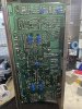
Well, damn! Stupidness befell me once again. In placing the new potentiometers on the board it occurred to me that they would be BEST on the BOTTOM SIDE! So I’m going to desolder all of them and carefully resoldering them to the BOTTOM SIDE of the board because why do we want to search for a 1/4” blue square in a cluster of other potentiometers and wiring like a birds nest trying to make a fragile adjustment and that way would be better than leaving them in the open clear underside where no interference exists!

this was the actual conversation I had with myself today! Rotflmmfao!
 
Doesn’t this just look more logical? I had to be super careful soldering them in Even with a pin tip iron.
 

Attachments

  • FA5FCD9E-AD53-42BC-83B7-52B69D2375FE.jpeg
    FA5FCD9E-AD53-42BC-83B7-52B69D2375FE.jpeg
    169 KB · Views: 76
  • 596FDCE3-FEC9-4A03-A9B5-472AC5A49E2D.jpeg
    596FDCE3-FEC9-4A03-A9B5-472AC5A49E2D.jpeg
    171.5 KB · Views: 71
  • 6B8BAD70-C5B0-46D7-BEBB-E1BA52E0D540.jpeg
    6B8BAD70-C5B0-46D7-BEBB-E1BA52E0D540.jpeg
    163.3 KB · Views: 72
  • 27CA5F75-7A6E-4E6D-9C09-15EB14DD28B1.jpeg
    27CA5F75-7A6E-4E6D-9C09-15EB14DD28B1.jpeg
    145.6 KB · Views: 60
  • 4ACAF987-0B71-4545-8AB9-F415B70B6144.jpeg
    4ACAF987-0B71-4545-8AB9-F415B70B6144.jpeg
    146.4 KB · Views: 61
  • FEE292E8-413E-4EFB-AFAE-8087DA601839.jpeg
    FEE292E8-413E-4EFB-AFAE-8087DA601839.jpeg
    157.7 KB · Views: 58
  • B2BD3F21-14D7-4495-98BC-8CA9F3BB15CD.jpeg
    B2BD3F21-14D7-4495-98BC-8CA9F3BB15CD.jpeg
    84.1 KB · Views: 65
I cleaned the plunger and switch actuator parts and re greased everything.
 

Attachments

  • 460F0B81-08CB-49FB-BA42-A5E58861394B.jpeg
    460F0B81-08CB-49FB-BA42-A5E58861394B.jpeg
    121.8 KB · Views: 59
  • 0F06C379-D8B5-49FB-BF77-F8E5197C0D9F.jpeg
    0F06C379-D8B5-49FB-BF77-F8E5197C0D9F.jpeg
    76.3 KB · Views: 54
  • C86E0A9C-03C4-4664-A5C0-1D4A73807BD8.jpeg
    C86E0A9C-03C4-4664-A5C0-1D4A73807BD8.jpeg
    99.3 KB · Views: 52
  • 6CEAE20E-001E-4C48-A756-125773B5A0F1.jpeg
    6CEAE20E-001E-4C48-A756-125773B5A0F1.jpeg
    137.2 KB · Views: 52
  • 1F62F262-1B24-4569-9BD5-A8D4FF317940.jpeg
    1F62F262-1B24-4569-9BD5-A8D4FF317940.jpeg
    78.4 KB · Views: 53
  • 1F9C24A6-83CC-4C72-B119-5DA150A5F1E7.jpeg
    1F9C24A6-83CC-4C72-B119-5DA150A5F1E7.jpeg
    90.6 KB · Views: 55
  • 36637554-83AA-4A1E-BABB-1B6C6C7301C1.jpeg
    36637554-83AA-4A1E-BABB-1B6C6C7301C1.jpeg
    83.1 KB · Views: 57
  • 4B33C636-F098-4E08-B668-00C084EF52DF.jpeg
    4B33C636-F098-4E08-B668-00C084EF52DF.jpeg
    78.4 KB · Views: 54
  • A0F7DC45-65BC-498C-BF52-39F6D697AA7F.jpeg
    A0F7DC45-65BC-498C-BF52-39F6D697AA7F.jpeg
    66.3 KB · Views: 57
  • A5A0F4E3-408F-41CD-91BC-DC502699A02B.jpeg
    A5A0F4E3-408F-41CD-91BC-DC502699A02B.jpeg
    82.2 KB · Views: 59
Hey @Sinder, yes the syscon board will be reworked as well and yes with the same effort but I won't start anything else until the preamp board is back in and tested. Since you also do this type of work, do you see anything I haven't done that could make an improvement?
Hi Steve, not yet. You are in the electrical conversions. In the Syscon you can replace all of the Greatz rectifiers. Then take higher dimensioned components. Or e.g. for D1 / D9 BWY74 / 76. Don't forget C46. For the change of both trimmers 9.525 and 19.05 cm / s to 5 K, I will report later for the correct series resistors.
Keep it up, it's worth it for these devices.
Mechanics later. LG

Uh, trimmer, blue are you putting up again?
That looks cheap. Didn't read the text, I'm on my way.
What looks cheap?
 
What looks cheap?

That doesn't fit at all, doesn't work at all.
You have done such a nice job so far. I would be happy if you continue to be professional.
LG André


here I've changed that too...
 

Attachments

  • FEE292E8-413E-4EFB-AFAE-8087DA601839.jpeg
    FEE292E8-413E-4EFB-AFAE-8087DA601839.jpeg
    433.3 KB · Views: 66
  • Akai GX 635 Black_0004.jpg
    Akai GX 635 Black_0004.jpg
    126.5 KB · Views: 66
  • Akai GX 635 Black_0073.jpg
    Akai GX 635 Black_0073.jpg
    113.5 KB · Views: 66
Ok
That doesn't fit at all, doesn't work at all.
You have done such a nice job so far. I would be happy if you continue to be professional.
LG André


here I've changed that too...
So I’m understanding you correctly, the “blue” trimmers look cheap because they’re dimensionally wrong and they’re raised up off the board because of the dimensional difference and being super hard to solder in because of that, and the fact I didn’t spray conformal coating on the board afterwards. Or is it the two wires I didn’t solder onto the board. I’m very open to constructive criticism and I’m sensing we may have a bit of a language barrier that must be overcame. I’m trying very hard to understand what exactly it is that I did or am doing that you’re not liking. You keep using the words “be professional” and I’m just not quite sure how to take your comments at the moment. Like I said, I’m very open to constructive criticism, if it’s the blue bourn trimmers that you don’t like and know of something that would work better then by all means give me the dimensions and product name and I will change them all out to what you suggest. If you think it looks more professional to spray conformal coating I have one problem with that (spraying it before testing) if there’s a problem that I need to re address on the board then it’s much harder to remove a component once conformal coating has been applied rather than before the coating has been applied. I have conformal coating but I’m not at that point yet and I do not always use conformal coating on every job I do. Thank you again for your insight @Sinder and I’m looking forward to your clarification.
 
Ok

So I’m understanding you correctly, the “blue” trimmers ......

very difficult indeed ...
No, by professionalism I meant: the trimmers belong on the component side, not on the conductor side. That's all.
I used to work in a radio production facility. If we had placed components on the circuit board from below, these would not have come through the TKO.
The trimmers, whether from Piher or the blue ones, don't matter. They are encapsulated.
I thought it could be seen that I needed the black trimmers back on the component side.
It doesn't matter whether you work according to your own standard, the state of the art or the ESA standard.
It is also not against you, but about the execution of the work. I've been doing this work for over 30 years.
So I thought it was good to watch your work. Understand it as a well-intentioned tip. If not, never mind. Do what you think and think is right. So I just read along.
best regards

with sealing ...

no one does, I know. If I sell my devices, they should have the best status at the time. I would be glad to be able to buy such devices.
Can you see later in the course. When images from measuring or tools such as hair angles are used for head adjustment.

 
here are pictures Mechanic Tonkopf
 

Attachments

  • 20190412_110014.jpg
    20190412_110014.jpg
    89.5 KB · Views: 60
  • 20190414_122623.jpg
    20190414_122623.jpg
    97.3 KB · Views: 60
  • 20190619_121636-2.jpg
    20190619_121636-2.jpg
    100.4 KB · Views: 59
  • 20190414_122916.jpg
    20190414_122916.jpg
    52.3 KB · Views: 61
very difficult indeed ...
No, by professionalism I meant: the trimmers belong on the component side, not on the conductor side. That's all.
I used to work in a radio production facility. If we had placed components on the circuit board from below, these would not have come through the TKO.
The trimmers, whether from Piher or the blue ones, don't matter. They are encapsulated.
I thought it could be seen that I needed the black trimmers back on the component side.
It doesn't matter whether you work according to your own standard, the state of the art or the ESA standard.
It is also not against you, but about the execution of the work. I've been doing this work for over 30 years.
So I thought it was good to watch your work. Understand it as a well-intentioned tip. If not, never mind. Do what you think and think is right. So I just read along.
best regards

with sealing ...

no one does, I know. If I sell my devices, they should have the best status at the time. I would be glad to be able to buy such devices.
Can you see later in the course. When images from measuring or tools such as hair angles are used for head adjustment.
Please understand I took no offense to what you were saying or have said, I merely could not understand exactly what you were getting at (like I said probably a language barrier) anyhow, I don’t have your level of experience in this work only a few years so I am always learning something new everyday. I appreciate you sharing your expertise with me, I noticed in your pictures that you also had your trimmers soldered on the mask side of the board rather than the component side. My reasoning was this, yes you can make adjustments from the inside cavity of the amp board, but how much easier would it be if the trim pots were on the mask side where it’s super easy to access them and be able to make fine adjustments without pulling wires or connectors loose accidentally (my hands are big) that’s my reasoning for placing the trimmers on the mask side rather than component side. Also, I mentioned in my first post in this thread that I have done RTR restorations but I have never restored an Akai GX635D so this is somewhat new territory to me. I would like to do the upmost professional job possible with this machine so any tips tricks or better ways of doing things I’m definitely all ears! I do appreciate your feedback! I’m not working by any standard, I am merely working by logical thinking and approach. I would give anything to have the countless years of experience you find on AudioKarma. I can only hope to one day be as good as the folks here on this site, I aspire everyday to learn from and create my own style though maybe a little unorthodox, I do try. Please feel free at any point to step in and offer advice as I am still a blank canvas somewhat and a sponge when learning. Although it may seem unorthodox to place the trimmers on the mask side, I reordered the piher 10% 10mm trim pots so that they would look more professional in place of the blue trimmers.
 
Hi Steve, no, I didn't think you were offended. I don't want to stop you from working or restoring the Akai GX 635 anymore. The blue trimmers were good too.
It just looks better if all components are also inserted on the component side.
It was mainly designed so that automatic measuring stations could put their contacts on the conductor side from below. Components would interfere. You can also access the trimmers from below through the openings for adjustment.
Let's leave it at that. We are waiting for your further pictures on your Akai. The cleaner and nicer you work, the nicer and better the result. You are on a very good path.
Greetings from Germany / Stralsund from André

Look, I also took these trimmers on one of my machines:
 

Attachments

  • 20180927_095048.jpg
    20180927_095048.jpg
    169.6 KB · Views: 61
Tell you what, @Sinder Please give me your ingredients and parts locations. You can make this job I have a breeze for me rather than taking me so much time to complete. You would be making my life so much easier and I'm being very serious about my request. Your work is awesome and exactly what I'm envisioning with this machine.
 
Hi Steve, did I understand that correctly? Do you want to send me your machine for conversion and revision?

I already wrote: I live in Germany.

I am happy to support you here in the forum. It would be nice if you had good measuring equipment for the comparison.
I think there are just as good people with you in the USA as here in Germany. In this forum there are guaranteed people who will help you on site if necessary.

Or did you mean: you want a component recommendation for your device and technical support during your revision?

As I already wrote, your pictures tell me your good expertise in this work on the device.

I'd rather ask about Steve again.
Or did you mean when converting this picture?

Explain it to me again.

Greetings from André
 

Attachments

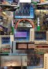
  • Collage-Ebay-Rep-02.jpg
    Collage-Ebay-Rep-02.jpg
    162.9 KB · Views: 64
  • Unbenannt-1.jpg
    Unbenannt-1.jpg
    180.4 KB · Views: 63
  • Zählwerk-Abweichung.jpg
    Zählwerk-Abweichung.jpg
    102.2 KB · Views: 64
  • 20190213_121345.jpg
    20190213_121345.jpg
    61.6 KB · Views: 65
Hi Steve, did I understand that correctly? Do you want to send me your machine for conversion and revision?

I already wrote: I live in Germany.

I am happy to support you here in the forum. It would be nice if you had good measuring equipment for the comparison.
I think there are just as good people with you in the USA as here in Germany. In this forum there are guaranteed people who will help you on site if necessary.

Or did you mean: you want a component recommendation for your device and technical support during your revision?

As I already wrote, your pictures tell me your good expertise in this work on the device.

I'd rather ask about Steve again.
Or did you mean when converting this picture?

Explain it to me again.

Greetings from André
What I was saying exactly is that you are doing the same work in your pictures as I plan on doing to this machine and I wanted to see if you could provide me with a parts list or exactly which components you changed out and their locations. I can do the work myself that’s not a problem, I just want to make sure that I build this machine pretty much like the one in your pictures using the same value components you’ve used. This is my first 635 restoration and if I’m going to do a full restoration and document it here on AK then I want to make sure that I’ve done the necessary component changes that are necessary which I see you’ve done. You have a lot of component changes judging by your pictures. I would just like a list of the changes if you could possibly provide me with that. I want anyone who reads this thread to see the success and failures that I will encounter but at the end if they use this thread as a guide then they too will be able to update their machine much like you’re doing and I want to do. Thank you, if you need anymore clarification please let me know. I’m not looking to copy you but rather make any necessary changes in order to enhance this machine to its best ability.
Steve

p.s. I made another parts order today as I’ll be changing the blue bourn trimmers to amphenol 10mm horizontal trimmers. I also ordered the ksc1008C to replace the 2sd571 on the amplifier board. The only components I haven’t changed on that particular board are the resistors, and any capacitors other than the electrolytics. Sorry, no pictures today, I will post as soon as my parts arrive which will be tomorrow sometime.
 
Hi Steve, did I understand that correctly? Do you want to send me your machine for conversion and revision?

I already wrote: I live in Germany.

I am happy to support you here in the forum. It would be nice if you had good measuring equipment for the comparison.
I think there are just as good people with you in the USA as here in Germany. In this forum there are guaranteed people who will help you on site if necessary.

Or did you mean: you want a component recommendation for your device and technical support during your revision?

As I already wrote, your pictures tell me your good expertise in this work on the device.

I'd rather ask about Steve again.
Or did you mean when converting this picture?

Explain it to me again.

Greetings from André
Well I have a question @Sinder, is that a gx635D in your photos with a digital counter and did that come standard on that machine Or is that your creation? Really nice work, also, what’s with all the black foam around the mechanical cavity is that for sound deadening or did that too come as part of the Original machine. Seems I have so much to learn about these machines it’s mind boggling to think about.
 
Back
Top Bottom