• The move to the new server is done. There are some software and database maintenance updates in process. This has us passing the hat around to help out. We appreciate any donations. Seriously, even a dollar helps. The payment page may be found here - https://www.audiokarma.org/support.html

KNielsen

Well-Known Member
Hey AK
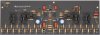
I'm starting this thread to share this build, and hopefully get some feedback while doing so.
It's gonna be an expensive build, so slow process is suspected :) The chassis that'll suit the 8pnp/npn will be from Modushop; 5U/400mm
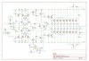
There are some adjustments to the old schematic I'm posting (the one I have on my phone):
D3 to D6 has been skipped in favour of a T3 led diode, R6/7 must be recalculated. Also I've added 10ohm base-resistors to the outputs in the later schematic and drawings on the PCB (I'll post the updated schematic tomorrow).
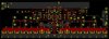
The layout is almost complete, but I have second thoughts about how to couple the DC-servo.
Should R24 meet R18 before the output transistors? The layout of the PCB, R24 meets at the speaker output, this made the layout way more simple.... But is this ok??

Best regards
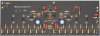
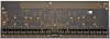
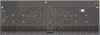
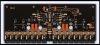
3D.jpg F.copper.jpg B.copper.jpg Silkprint.jpg
 
Register to hide this ad
You might want to simulate this design before committing to a fab perhaps. Pretty aggressive design, have you done this before?
R24 placement is not critical
Probably want a jfet opamp for a dc servo too. I use opa2134 in a different arrangement
 
You might want to simulate this design before committing to a fab perhaps. Pretty aggressive design, have you done this before?
R24 placement is not critical
Probably want a jfet opamp for a dc servo too. I use opa2134 in a different arrangement
Thanks for reply. The opamp is OP37G.
Yes I do need to simulate, especially the BIAS-section if it will run stable, or it needs more attention. The basic layout and inspiration is from Acurus A250 pared with some twists form the Aragon 8008 amplifier.....
Btw I'll order the cheapest PCB for test, before going all-in in thick PCB's with a descent amount of copperweight ect...

Best regards
 
Yes I see you spec'd a op37, precision bipolar with bias current comp, your choice :)
pcbs are cheap, I use jlcpcb, adding 2oz copper cost some more but you can open up the solder mask in the high I areas and spec HASL plating which will add extra I capacity.
I do not see many designers here at AK, you would get more design input at DIYaudio, where I also participate. if you have your ltspice sim entered that would open the doors for more input and analysis.

Good luck
 
Yes I see you spec'd a op37, precision bipolar with bias current comp, your choice :)
pcbs are cheap, I use jlcpcb, adding 2oz copper cost some more but you can open up the solder mask in the high I areas and spec HASL plating which will add extra I capacity.
I do not see many designers here at AK, you would get more design input at DIYaudio, where I also participate. if you have your ltspice sim entered that would open the doors for more input and analysis.

Good luck
I have not been working with fets before, so all bipolar. I have a good handful of op37's, so it came in first:)

I'll try diyaudio later

Best regards
 
jfet opamps go way back for me to TL07x, LF15x series, might be older tech than you are :)
parts are in scare supply, stock up for your builds, I can not find mjl1302 or mjl3281 anywhere reputable, njw are almost in the same situation
 
jfet opamps go way back for me to TL07x, LF15x series, might be older tech than you are :)
parts are in scare supply, stock up for your builds, I can not find mjl1302 or mjl3281 anywhere reputable, njw are almost in the same situation
I'm quite new to electronics, so you could very well be right;)
Mjl1302/3281 is stock again mid 2022 accordingly to Mouser:confused:.... The market is really s**t right now....
I have 8 of both mjl1302/3281, enough to make a single prototype board, and a ton of time for testing as the market is with parts at the moment
 
Last edited:
My honest opinion as you being new to electronics, I think you are too aggressive on this design, especially if it is your first power amp design.
As I have, buy, read Bob Cordell's power amp design book. Simulate your design first. If anything, you will learn electronics and analog design with simulation which is a pre-requisite these days.
As a pcb designer, it is best to start with the system requirements, then your costing, and then the market if that is the case.
I am working with Bob Cordell on the BC-1 design in a 3Ux300mm dissipante chassis, its is designed, running, tested, clean up phase.
In my proto, I have a Triad 90VCT/500VA toroid transformer, 2 pairs of mjl3281/0381, a new PS pcb, it will blow the doors off your house with just that configuration. It is good enough for most.
Above is a low cost design, but still, $ adds up fast.
I am unsure why you need 8 pairs, three pairs imo would be the limit for a residence unless you are building a large PA system.
What speakers plan to be used with the amp, efficiency, wattage, ohms?
Even then, it might be better to have more amps to go with more speakers., systems approach
The industry for that power level is going class D

Design wise I can add for the best thermal bias stability, it is best to sense the temp on all 3 stages of the 3EF Bart N. Locanthi "T circuit" topology design
Which means it is best to have a Vbe generator sensor devices, on the pre- & drivers & on the main OPS heatsink (better if mounted on one of the bjts or a thermal track device)
There you go, my input, take it or leave it :) Good luck
 
Last edited:
@rcs16 very good feedback. I'll look into your advices, especially the last part for added stability..
Regarding the "more-then-needed"-approach, I listened to an extreme DIY a couple of years ago. It did something I have never heard before, and oversized suddenly had a new meaning.
My own is gonna be 2x1.5-2kVA xformers. Haven't desided if it's as a dual set or dual windings in one xformer.
 
Last edited:
One last word of advise create a separate front end driver and ops pcb possibly
I actually started this way..... Maby I'll return;)
So far I added a PNP and a diode to the NPN-bias network to hopefully make it more stable if needed. There were space enough to make this happen on the PCB without starting all over...

Best Regards and thanks for advice
2021-10-31_221953_bias_1.2.jpg 3D Rev1.2_10-21~2.jpg 3D Rev1.2_10-21_back~2.jpg
 
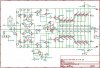
I was pointed towards a series resistor connection above Q15 (PNP) to support Q16 (NPN) in the bias network. From explanation this seams as a very reasonable solution.
The BIAS-network has been altered to meet this, also with a dedicated VBE-pot placed on the PCB.
Sorry for all the pictures.... It's all I have before ordering a real PCB for testing:)
Schematic Rev1.3_11-21.jpg 2D Rev1.3_11-21 Front.jpg 2D Rev1.3_11-21 Back.jpg
 
You might want to simulate this design before committing to a fab perhaps. Pretty aggressive design, have you done this before?
R24 placement is not critical
Probably want a jfet opamp for a dc servo too. I use opa2134 in a different arrangement
Looking at the Jfet opa2134 , it's a dual modul Vs the one I selected.
The easy one would be to select a opa134, if this is better then a op37.... I'm new to DC-servo, and 'Elliott Sound' don't provide any info on dual layout DC's....
How do this work, if you use both internal opamps in a 2134, witch I believe you do?

Regards
 
Final layout! :) Back and fourth and so on.. Tried different approaches, also with a DC-protection included onto the main board for each channel.
Never the less, this is final, as short and straight coppertraces as possible, no nice to have aplications beside from the needed. All groundconnections on the PCB will meat at an equal distance to the connection to the common starground in the PSU later on.
Attached is a picture with full view of the components, plus some PDF's of button- and frontcopper and frontsilk screen.
new.jpg
 

Attachments

Last edited:
Good luck with your design looks good. I could comment on design choices but what matters is if it works, the experience and the enjoyment of the journey.
I have my Cordell BC-1 power amp up and running since our last exchange

To answer your previous question, a dual opamp as a dc servo would have the first stage as your inverting integrator and the second stage as a unity gain inverter
 
Does the board mount a little offset on the heatsinks?

The heatsinks on the 5U are two per side with a vertical split right down the middle, if that matters to the attachment of the center device (Q15?).
 
Does the board mount a little offset on the heatsinks?

The heatsinks on the 5U are two per side with a vertical split right down the middle, if that matters to the attachment of the center device (Q15?).
Ohh ****.... Good question.. the layout states dead center for Q15 as the board is roughly 390mm with the 5U I've looked at being 400mm internal. Damm...
The 5U 500mm would be overkill.

Do you know the width of the centersplit in 5U??
 
They are butted "tight" but I don't know the actual gap as it may be, between each 200mm deep section. I used the 4U 300mm for my F6 build, but those are one whole chunk of heat sink per side.

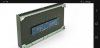
5U is shown below.


Screenshot_20220218-111026_Edge.jpg
 
They are butted "tight" but I don't know the actual gap as it may be, between each 200mm deep section. I used the 4U 300mm for my F6 build, but those are one whole chunk of heat sink per side.

5U is shown below.


View attachment 2488442
Ok, thanks for the picture. I can cut of a few mm of the edge on the PCB before ordering, that should be enough for a bit offset.
 
Back
Top Bottom