

You are using an out of date browser. It may not display this or other websites correctly.
You should upgrade or use an alternative browser.
You should upgrade or use an alternative browser.
Amplifier build
- Thread starter KNielsen
- Start date


Andersonix
New Member
I see you kept on adding PS caps, now one set for each transistor! How are you deciding how much is enough?
A discussion at diyaudio.com made me conclude that those decoupling caps must be >at< the pins of the output transistor, which you seem to have accomplished pretty well.
A discussion at diyaudio.com made me conclude that those decoupling caps must be >at< the pins of the output transistor, which you seem to have accomplished pretty well.

KNielsen
Well-Known Member
First design was 1x 220uf/2.7uf at each rail.I see you kept on adding PS caps, now one set for each transistor! How are you deciding how much is enough?
A discussion at diyaudio.com made me conclude that those decoupling caps must be >at< the pins of the output transistor, which you seem to have accomplished pretty well.
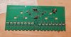
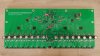
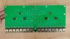
I looked it over and found that the space on the PCB allowed a much closer connection to the outputs (a good thing) if smaller value of caps were selected due to smaller diameter.
It's now 8x paralleled 47uf/0.47uf pr rail.
Soundwise or how much capactiance is needed??; to be honest I have no clue yet if this this is gonna sound "just right".. But generally I prefer some capacitance after the PSU, and found the new layout to fulfill this aspect
Edit: at one point I'm also afraid of adding to much uf after the fuse, making it useless
Regards
Last edited:

KNielsen
Well-Known Member
First "simpel test" after some swing in the megahertz region that needed attention!
I didn't manage to fix this with the DC-servo for now, so skipped it in favour of an RC-network so I could focus on the rest of the build.
R17 is pulled and replaced with a 2Kohm/470uF to ground to do the feedback. I actually wanted to use a 1Kohm/1000uF as RC, but didn't have the 1000uf in my office, so scrambled what I had to do this
All KSP42/92 has been replaced with KSA992/KSC1854 and the pre-drivers are now KSA1381/KSC3503.
R5 is 56K with the LED diodes currently installed.
R6/R7 is now 475ohm, but might try 511ohm to see if I overdoo the diff-current...
At the BIAS-circuit the PNP/R26/R27 hasn't been tried and still bypased.
I have no heatsink for the amp-module yet, so it's pretty low BIAS: 2mV at the emitters(!!), so I don't harm the output transistors due to heat...
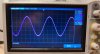
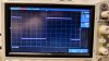
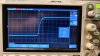
All curves is 2mVpp from the signalgenerator, so also in the lower end of the scale:
1kHz Sine
50kHz sine
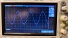
1kHz square
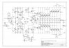
Original schematic
The rails are 64VDC for now, DC-offset is approx 8mV though the transistors hasn't been matched in this pre-build
Best regards
I didn't manage to fix this with the DC-servo for now, so skipped it in favour of an RC-network so I could focus on the rest of the build.
R17 is pulled and replaced with a 2Kohm/470uF to ground to do the feedback. I actually wanted to use a 1Kohm/1000uF as RC, but didn't have the 1000uf in my office, so scrambled what I had to do this
All KSP42/92 has been replaced with KSA992/KSC1854 and the pre-drivers are now KSA1381/KSC3503.
R5 is 56K with the LED diodes currently installed.
R6/R7 is now 475ohm, but might try 511ohm to see if I overdoo the diff-current...
At the BIAS-circuit the PNP/R26/R27 hasn't been tried and still bypased.
I have no heatsink for the amp-module yet, so it's pretty low BIAS: 2mV at the emitters(!!), so I don't harm the output transistors due to heat...
All curves is 2mVpp from the signalgenerator, so also in the lower end of the scale:
1kHz Sine
50kHz sine
1kHz square
Original schematic
The rails are 64VDC for now, DC-offset is approx 8mV though the transistors hasn't been matched in this pre-build
Best regards
Last edited:

Very cool stuff!

KNielsen
Well-Known Member

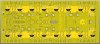

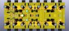
they look impressive, and open hardware too... do you have them on github as well, I could learn a thing or 2 studying the schematics.Some better pictures of the board
View attachment 2794159 View attachment 2794160 View attachment 2794161
What kind of PS are you going to use? If you don't mind the asking.
Thanks for posting them.
KNielsen
Well-Known Member
The open source logo is due to the fact that I'll share my final "fully working" project later. All schematics and layout (files pr Kicad) will be shared. You'll have to wait just a bit longerthey look impressive, and open hardware too... do you have them on github as well, I could learn a thing or 2 studying the schematics.
What kind of PS are you going to use? If you don't mind the asking.
Thanks for posting them.
all Gerber's will be included for ordering at JLCPCB and other Gerber's for ordering at PCBWAY if one like this better.Regards