

You are using an out of date browser. It may not display this or other websites correctly.
You should upgrade or use an alternative browser.
You should upgrade or use an alternative browser.
Amplifier Distortion, DC-Offset, and You!
- Thread starter EchoWars
- Start date


MegaHurts
Super Member
I don't think it's the same thing, but could be wrong. It might send the other channel signal to the right channel but that doesn't account for the other channel itself with caps/transistors/resistors...This is a great thread and until recently I never knew to test for this before. Last year I recapped my old Heathkit AA-1800 power amp. It's paired up with the matching AP-1800 preamp. I didn't attempt any output bias adjustments (although the procedure is provided in the users manual). I'm not really skilled with a multimeter but today I finally used one to check things out, so I'm posting this as a sanity check. I set the preamp controls as advised and using the "B" speaker setting I disconnected the wires connected to the right channel speaker since it was easy to get to. With the amp having idled for about 30 minutes and the multimeter set at 200m DC I got a reading of 4.4. Instead of disconnecting the wires at the left channel speaker and testing at that point I simply used the "reverse" feature on the preamp which sent the left channel signal to the right speaker where I was already set up. I got the same reading (4.3 - 4.4). Does all this sound legit?

JamVal
Addicted Member
Is 'The Fisher 700-T' Capacitor Coupled instead of DC?

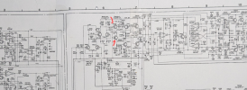
The center voltage adjustment in the SM calls for placing two 10K ohm resistors in series across the filter cap, (not the coupling cap for each channel) and then measuring DC from the junction of those two resistors to the junction of the resistors with the arrow 'Center voltage' in the above schematic. Is this the procedure for adjusting DC offset on a cap coupled amp?

The center voltage adjustment in the SM calls for placing two 10K ohm resistors in series across the filter cap, (not the coupling cap for each channel) and then measuring DC from the junction of those two resistors to the junction of the resistors with the arrow 'Center voltage' in the above schematic. Is this the procedure for adjusting DC offset on a cap coupled amp?
JamVal
Addicted Member
Thanks, Ylli, I was able to get a couple of 10K ohm resistors today and went ahead and did it according to the SM. Both channels were a bit high. There's plenty of adjustment room on the pots to bring them down to zero and negative readings. The pots are a bit jerky and probably could benefit from a cleaning, but they are a bit buried.
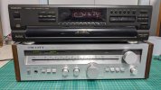
Unrestored QRX-7001 with unknown issues:
System A
Front Right: 66mV / 16mA
Front Left: 210mV / 0mA
Rear Right: -40mV / -10 mA
Rear Left: 300mV / 82mA
System B
Front Right: 65mV / 28mA
Front Left: 211mV / 0mA
Rear Right: -40mV / -14mA
Rear Left: 300mV / 97mA
Looks like I have some work to do tracking down the left channel to see what is wrong.
System A
Front Right: 66mV / 16mA
Front Left: 210mV / 0mA
Rear Right: -40mV / -10 mA
Rear Left: 300mV / 82mA
System B
Front Right: 65mV / 28mA
Front Left: 211mV / 0mA
Rear Right: -40mV / -14mA
Rear Left: 300mV / 97mA
Looks like I have some work to do tracking down the left channel to see what is wrong.
Last edited:


Puddintane
Super Member
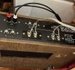
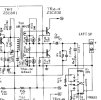
Question if I may. Can I measure the offset on a very basic receiver (Realistic STA-35B) that has connections for only a single pair of speakers? Actually, it does also have a single set of RCA jacks for speakers. Do I connect speakers for a “load” and then test at the same jacks? Or can I test at the RCAs? Thanks.
kirk hawks
New Member
I just put my Denon PMA-700V back into service, the right channel was going in and out sounding distorted/dropping out completely. DC offset was +2.9mV left, and -76.4mV right. Bias was at about 8mA at both test points.
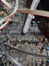
I hooked up my mission ms-50's for testing and used a glue stick to tap around on the board, eventually I found TR409 and TR413 were the culprits. The joints were dry/wiggly. Flux and soldered them, I could not find any other loose components. I then remeasured DC offset and it was close to 0mV both channels.
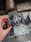
I would like to repair this speaker terminal mess, I have read some other posts on this but am asking if anyone has links to purchase the posts/parts. I believe there is someone in Germany selling repair posts but it costs a lot to ship to Colorado.
So I have read there is some kind of feedback circuit in this amplifier design (regarding DC offset?)and would like to learn more about how it works. Can anyone educate me or point me in the right direction please? Yes, I am broadcasting my ignorance
I now have my resurrected speakerlab Delta I type 4s back in service as "S40"s, as they were bastards to begin with. Paul at the loudspeaker store helped me with new 8 in and 10 in drivers, and I also modified the crossover to be nestorovic by adding in a 200uF cap and 2.7 ohm res in series with the 10 in driver. It turned out I needed new tweeters as well, this setup sounds great now even though I cannot hear much above 12kHz haha! I am happy with my wiim pro and cannot really hear any difference between spotify 320kbs, or qobuz "hi-res" flac downloads.
I hooked up my mission ms-50's for testing and used a glue stick to tap around on the board, eventually I found TR409 and TR413 were the culprits. The joints were dry/wiggly. Flux and soldered them, I could not find any other loose components. I then remeasured DC offset and it was close to 0mV both channels.
I would like to repair this speaker terminal mess, I have read some other posts on this but am asking if anyone has links to purchase the posts/parts. I believe there is someone in Germany selling repair posts but it costs a lot to ship to Colorado.
So I have read there is some kind of feedback circuit in this amplifier design (regarding DC offset?)and would like to learn more about how it works. Can anyone educate me or point me in the right direction please? Yes, I am broadcasting my ignorance
I now have my resurrected speakerlab Delta I type 4s back in service as "S40"s, as they were bastards to begin with. Paul at the loudspeaker store helped me with new 8 in and 10 in drivers, and I also modified the crossover to be nestorovic by adding in a 200uF cap and 2.7 ohm res in series with the 10 in driver. It turned out I needed new tweeters as well, this setup sounds great now even though I cannot hear much above 12kHz haha! I am happy with my wiim pro and cannot really hear any difference between spotify 320kbs, or qobuz "hi-res" flac downloads.
Attachments

GameOverUK
New Member
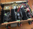
Hello, I have a question, I bought a Denon POA-T3 and in the service manual it says adjust to 2mV +/- 1mV the idle current, do you think it is correct in the manual? It seems very low to me.


Last edited:

It actually says 2 +/- 0.5mV. That's the voltage at the test point. It doesn't tell you what the actual idle current is when the voltage at the test point reads 2mV. I'd recommend just doing as directed by the service manual.
GameOverUK
New Member
Thank you, I adjusted it according to the service manual, it came out almost perfectly (was between 3 to 4,5mV before).It actually says 2 +/- 0.5mV. That's the voltage at the test point. It doesn't tell you what the actual idle current is when the voltage at the test point reads 2mV. I'd recommend just doing as directed by the service manual.
Bias: Left/Center/Right: 2/2/2mV
Offset: Left/Center/Right: 0/0/0,1mV
RabbertKlein
New Member
Hi all,
Nothing like keeping a thread going that is old enough to buy a legal drink!
I just acquired a personal grail receiver... a Scott R77S, the last of the US made units. I was so excited to hook it up, so I went through the usual steps... make sure the fuses are the right value, check DC offset... uh oh. Right channel: 23 mV or so. OK. Left channel: 1.5V. Yes, V. So hooking it up at baseline would be like connecting a battery to my speaker. No good. This receiver has no trim pot for DC offset. My gut says that DC offset that high doesn't come from mismatched transistors, but then again I'm no engineer.
The seller sold the amp as working and allowed people to try it out in store, so it presumably didn't kill his test speakers. Also, if it helps, it started out at something like a few hundred mV, and then as the amp warmed up, continued to rise and rise and rise. I went through the bias setting procedure because things were a little warm, and while that is now solved, it didn't affect the offset, probably surprising no one.
Thoughts? Other threads where I should be posting other than this one? Thanks!
Nothing like keeping a thread going that is old enough to buy a legal drink!
I just acquired a personal grail receiver... a Scott R77S, the last of the US made units. I was so excited to hook it up, so I went through the usual steps... make sure the fuses are the right value, check DC offset... uh oh. Right channel: 23 mV or so. OK. Left channel: 1.5V. Yes, V. So hooking it up at baseline would be like connecting a battery to my speaker. No good. This receiver has no trim pot for DC offset. My gut says that DC offset that high doesn't come from mismatched transistors, but then again I'm no engineer.
The seller sold the amp as working and allowed people to try it out in store, so it presumably didn't kill his test speakers. Also, if it helps, it started out at something like a few hundred mV, and then as the amp warmed up, continued to rise and rise and rise. I went through the bias setting procedure because things were a little warm, and while that is now solved, it didn't affect the offset, probably surprising no one.
Thoughts? Other threads where I should be posting other than this one? Thanks!
Welcome! Yes. Start a new thread in Solid State!Other threads where I should be posting other than this one?