• The move to the new server is done. There are some software and database maintenance updates in process. This has us passing the hat around to help out. We appreciate any donations. Seriously, even a dollar helps. The payment page may be found here - https://www.audiokarma.org/support.html

Amplifier Distortion, DC-Offset, and You!

Time for one of those long, boring semi-technical posts that no one here reads...

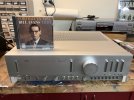
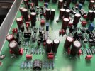
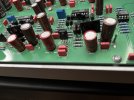
As a few of you know, I bought a rare Kenwood 700M amplifier a few weeks ago on eBay. It arrived with a weak channel which was taken care of by replacing a bypass cap. Since then, I have gone through the entire amp and replaced all the electrolytic capacitors with the exception of the big power supply caps (not that expensive...maybe $20 in caps).

The previous owner described the amp as 'perfect' sounding, and compared with the big Mac's and Krell's and such. Before buying it, he described his current system which was quite high-end. I assumed that since he owned expensive equipment that he knew what he was listening to.
:withstpd:

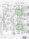
Got the amp back together today (parts finally in), and fired it up with my small Dynaudio's (can't use the Heil/Dynaudio's for this, as they are bi-amped). Ummm...it sounded like ass. OK, it didn't always sound like ass, but at low volume levels it was obvious that something was wrong. I had a pretty good idea what was going on, so I grabbed my meter. Sure enough, there was 100mV of DC offset in the left channel, and almost 250mV (!!!) in the right! 250mV is almost enough for the protection circuitry to kick in!! Not good. I pulled the driver boards out and replaced the amp input differential pairs for both channels with new Zetex HG PNP's ($5 in transistors, no biggie). DC offset is now about 12mV in both channels. An input pair being as unbalanced as the Kenwood was when it arrived probably generates 10x the distortion as a properly balanced pair, especially at low volume. If you would like to read more about the benefits of a balanced differential pair, read here.

OK, sit down for another listen. NOW we're cookin'!! Amazing night and day difference. I can honestly say that it is without a doubt the nicest amp I have ever listened to, and there have been more than a few that impressed me. The bottom end on this thing is as clear as spring water, and it has an openess that is difficult to describe. As for power, my dummy loads cannot take the power output of this thing, but I can crank it for 10-15 seconds without destroying them. Left channel - 218W before clip, right channel - 220W, this into 8-ohms. Totally cool!! I just have never heard bass like this...wow...

Bottom line...if you expect to hear great sound, you just might...regardless of the reality. The guy I bought this from was well-meaning, but did not know how to listen subjectively. His new spendy amps could be performing horribly, and his expectations of what he felt he was supposed to hear would rule out anything to the contrary.

Your own subjectivity could be suffering too, so give yourself a reality-check.

As a semi-poll, I'd like to see those on this board whip out their multimeters and take a look at the DC that is being presented to the speakers. This means..

1. Speakers disconnected (or connect the meter to the 'B' speakers and set the front panel speaker control accordingly)
2. Input set to an unusued position (not Phono)
3. Volume control at minimum.
4. Balance in center
5. Tone controls either defeated or set to mid position
6. Set your meter to read DC, and set to a low scale (300mV scale is common) Connect directly to the Pos and Neg of the speaker terminals
7. Give the amp 10 minutes to settle. Report back...I'd like to see how healthy all these old amps are.

If you read:

0 - 15mV: Damn good!! If you read '0V', you may have a capacitor output, or your meter is set wrong

16mV - 50mV: An acceptable value, especially at the lower end of this range. 2nd harmonic distortion is probably twice to four times what manufacturer's spec calls for at higher frequencies. Probably not audible, as the distortion is mostly in the upper octaves. At the upper end of this range I begin to raise an eyebrow. :saywhat:

50 - 85mV: Something is certainly amiss, and while this is not enough to put your speakers or equipment in jeopardy, the amp is running nowhere near where it should. I'd venture to guess that most of the DC-coupled amps that are in use by forum members here fall into this range.

100mV to ?: A high enough voltage will cause the DC protection to kick in. This happens at a level determined by the designer, but is usually equivalent to about a diode drop (600mV)or so. Needless to say, if you are listening to an amp with 100mV or more of DC offset, you have no idea what the amp really is supposed to sound like. Indeed, some amps without a differential input are actually designed to have a bit of DC at the outputs, but this is triple-rare, and I don't think anyone here owns one. (in my book it's piss-poor design, but if you can sell it WTH..)

Soooooo...go grab a meter and tell me what you find...


Sanyo P55 - as received, 150mv left, 75mv right. originally adjusted to about 10mv. Currently stable around 20mv both channels. Amp is unrestored. does run warm.
Sanyo Plus A35 integrated - as received 150mv left, 45 mv right. Adjusted and now 9mv left and 6mv right. Unrestored.
Sony TAN55ES - 30mv one channel 3mv the other. Unrestored and unadjusted
Dynaco ST150 - Amp originally built by me from kit circa 1975. not working properly, decided to dust off the textbooks and seek help here! Replaced differential transistors, capacitors and a few other components. Thanks! repaired and restored - 13&16mv.
Nakamichi 420. repaired. 3mv left 2.5mv right. (but no speaker protection)
Cyrus One HD (modern integrated originally bought for office due to small form factor and multiple inputs) only 4 years old, 35mv one channel, 10mv the other.

As an added bonus - thanks to everyone here willing to chip in with advice and help on trying to restore and repair these old devices - from someone with just a smidge of electronics background, I'm learning fast and greatly appreciate the willingness of people here to freely offer their expertise and advice. Not always said, but always appreciated.
 
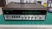
A new to me wood cased Harman Kardon 330B with 472 on the left and 480 on the right. o_O

It's on my bench hooked up to some test speakers and I've been using it for low volume FM listening since I got it about two weeks ago. Some bulbs needed replacing and all pots needed a good cleaning so it sounds fairly good but it does make the typical thump and another quick strange noise on startup with the speakers turned on. The 330B is cap coupled so the first suspects will be the coupling caps as they might be leaking.

I thought I was done with it but now it seems it's time to break out the schematic, DVM, iron, and a can or two of ISP to track the issue down.

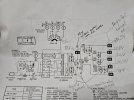
HK 330B Offset.jpg
 
Cap coupled as you noted. Make that offset measurement with the speakers connected - open circuit measurement is useless.
 
Make that offset measurement with the speakers connected
Thanks for the headsup! I was going by what EW said in the first post of this long thread (no speakers) but that was probably meant for direct coupled amps, not cap coupled. Being cap coupled with a single power rail, I think I'm looking more at DC balance than DC offset.

Anyhoo, with 8 ohm speakers attached, the readings became a more respectable 2.8 - 3.2 mv on both channels. Readings were the same with 8 ohm load resistors hooked up. To help me sleep at night, I think I better follow the service manual to make sure everything is as it should be inside before signing off on this one.

Am listening to strong FM on it right now and it sounds good. Real good. I like it!
HK 330 A B Adjust.JPG
 
A new to me wood cased Harman Kardon 330B with 472 on the left and 480 on the right. o_O

It's on my bench hooked up to some test speakers and I've been using it for low volume FM listening since I got it about two weeks ago. Some bulbs needed replacing and all pots needed a good cleaning so it sounds fairly good but it does make the typical thump and another quick strange noise on startup with the speakers turned on. The 330B is cap coupled so the first suspects will be the coupling caps as they might be leaking.

I thought I was done with it but now it seems it's time to break out the schematic, DVM, iron, and a can or two of ISP to track the issue down.

View attachment 3216485


i'd be looking at all the 2sc458 in it before worrying about the output caps. the 458s just need to be replaced. no need to use freeze spray. just shotgun them.

i've done a couple of these and most small value caps were starting to leak but were mostly in spec. they obviously need to go.
 
Just measured my Hitachi HMA-8300
50mv r
63mv l

Obviously it's in need of adjustment, time to pull out the service manual.....

50mv is the spec looks like only need to adjust one side
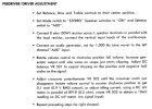
Manual states, there are different values for L/R in setting DC offset
right channel is 30mv set on the inside
10mv on the left side!
This should give 50mv dc offset.

Very interesting, looks like I need to pull my amp and adjust the L channel.
 
I purchased an good looking JVC A-X5 amplifier at auction (eBay) for about $45. Rated at 70 wpc and touting "Super A" amplifier technology. This was quite some time ago, before I gained a little (very little) technical knowledge about amplifiers. I bought it because reviews on Audiokarma (and other sites) touted it as being a superior amplifier. Hooked it up and promptly put it on the shelf to collect dust for well over 5 years. It went onto the shelf because it sounded terrible. I was still working (now retired) and didn't have time to look at it. Yesterday I decided to re-visit it. Hooked it up. Although the speaker relay worked perfectly and it played loudly (out of both channels), nothing else had changed. It still sounded like absolute crap. Took the cover off. Except for a little dust, everything looked perfect. No leaking capacitors, no overheated resisters. Looked pretty darn perfect for an amplifier that was sold somewhere around 1980.

I then had an inspiration. Having built a power amplifier (my first) last year, I knew that there should be an adjustment for biasing the output devices. Found a free service manual on-line. Downloaded and printed it. Hmmmmm. According to this manual, the amplifier has adjustments for (left & right) Center Voltage and (left & right) Idling Current on TAP-280 board. Study the schematic. I identify the circuit diagram for the TAP-280 board. Then I identify the test points referred to in the manual. These include Ground, TP-2, TP-6 and the emitter for X353 and X536. Find X536 after a little searching but I cannot find X353 anywhere. Oh, it's a typo! They really mean X535. Which pin is the emitter? Oh, it's marked right on the PCB. Looking good!


I blew out the internal dust (small amount) and gently wiped down the inside boards and wiring so that I can better see the printed component markings on the board(s).
I start with the power amplifier "Center Voltage Adjustment". Per the service manual, voltage to be adjusted to +/- 10mv. Wow, that's a small hole in the PCB for my mini-screwdriver. Better be careful not to drop that screwdriver while the power is on. Hook up the test leads of my multimeter to the test points. Both channels way out in the weeds. Carefully adjust both the right and left channels to very close to zero mv. Now on to the "Idling Current Adjustment". Again, carefully hook my test leads up to the test points (2 & 6) and the emitter of the specified output transistors. Again, voltage readings completely out of spec. As the amplifier heats up, the "Idling Current" voltage readings fluctuate. After about 15 minutes, the amplifier settles down and I am able to dial-in the specified 12mv volts.

Next I cleaned (contact leaner) some of the controls including the tone and balance controls (a litttle scratchy) and the "Mute" switch. The "Mute" switch was introducing distortion into the right channel. Volume control was OK so I left it alone. Lastly I put the metal case back on (6 screws) and cleaned the exterior. Now the amplifier appears clean and shiny!

Now the real test. What does it sound like? Did these voltage adjustments make a difference? The change is amazing! This amplifier sounds every bit as wonderful as the reviews indicated. The amplifier is now crisp and detailed.

My only dilemna now is do I sell it or keep it? My wife has been bugging me to provide music for the lower level of our house ever since I moved the main system to the proverbial "man cave" in our large, remodelled attic. I like this integrated amplifier very much. But how much longer will it hold out before something fails? That's my dilemna. I'm 74 years old. Perhaps it will outlast me but, given it's age, it could fail in a couple of years. I guess I could deal with it then. I've never recapped/restored a vintage amplifier and am a little fearful of trying it.

What would you do?

Useful tools for this project:
- Clip leads for multimeter
- Large illuminated Magnifier on swivel arm (I purchased mine on Amazon for $50). The component markings on the circuit boards were difficult to see without the magnifier.
- Contact Cleaner
- Large cotton swabs on 6" sticks for cleaning internal dust off the boards.
- Alcohol as cleaning agent.
 

Attachments

  • IMG_1764.JPG
    IMG_1764.JPG
    62.7 KB · Views: 30
  • IMG_1755.JPG
    IMG_1755.JPG
    179.4 KB · Views: 30
  • IMG_1768.JPG
    IMG_1768.JPG
    125.8 KB · Views: 29
My only dilemna now is do I sell it or keep it?
No reason to get rid of it. Now that it's been cleaned and adjusted theres no reason to expect anything to fail. Doesn't look like any of the electrlytics are swollen, but you could replace the ones in the power supply section if you felt inclined. Calling it old made me chuckle a little. That's newer than anything I use by a decade. But then again I still think of the 80's when someone says 20 years ago.
 
NAD 7020 - original with analogue tuner..

Left channel: 2.5mV
Right channel: 35mV

Although the RHS is within manufacturer's tolerance (+/- 50mV according to the service manual) I think I'll tweak it the next time the lid is off to clean the pots / switches.. which I now need to do semi-regularly.. I gave it a full recap a year or two back and have done other 7020's - they're pretty easy to work on, if getting rather aged now..
 
Hi all

Does anyone know how to adjust bias on a Primare Pre30?
I do have, and uploaded, service manual. There're those RP1 to RP4.
But don't know where to take the mesures nor to what value should I adjust it, i.e. read it on the multimeter.
I've notice this 4 tips, uploaded pictures.

Help would be very apreciated.
Thank you
 

Attachments

  • IMG_3275.jpg
    IMG_3275.jpg
    146.7 KB · Views: 13
  • IMG_3274.jpg
    IMG_3274.jpg
    102.9 KB · Views: 13
  • PRE30 Service Manual.pdf
    PRE30 Service Manual.pdf
    675.1 KB · Views: 9
Screenshot 2024-06-10 104731.jpg
Voltmeter at the indicated point to ground. Adjust RP1 for as close to zero as you can. Repeat for sections 2, 3, and 4. Anything further, start a new thread.
 
Hi,

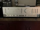
I have a Technics su 8099k with both channels arround 250mv. The main relay is clicking the same as the speakers relays. I've adjusted the amp with the service manual. Is this normal with this amp? Thanks.
 
View attachment 3222791
Voltmeter at the indicated point to ground. Adjust RP1 for as close to zero as you can. Repeat for sections 2, 3, and 4. Anything further, start a new thread.
Thank You for your help.
My contribute for this forum, Primare Pre30, not on speakears output cause is a pre-amp, so on output xlrs from pin 1 to pins 2 and 3, worst value was arround 10mv the others arround 5mv, after adjust all bellow 2mv.
 
I think we need the bias procedure for a given amp
If not yes we have some idea
some amps use temp control others voltage control
then there I don’t know control
I think to measure is a must but how to adjust or even measure correctly is complicated at times
the old receiver I got seems low
Just a few mv with no speakers and same with
I’m lucky to have been given the manual
This will help and is needed.
vintage needs to be tested and done with some experience
read and read is needed
 
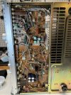
Trying to lower my left DC at 199 mv to something more acceptable level of my Luxman LV-105U. I am suspecting the cause might reside in this 1st differential circuit. Find this defect capacitor C7109, 47uf/16v while checking around. Measured at 300nf, thought I found the problem, so happy. After a new UFG47uf/50v went in. The DC instead of dropping, it goes up to 360mv! Can someone help? What did I do wrong? Or I am totally looking at the wrong area to lower the DC offset regardless of the cap replacement?
I did have a post here with not that many responses and hoping to get more attention if I may.
Thx in advance.

IMG_1632.jpeg
 
Good day. I have a 330b series-B2 device, which is a modded version of 330a. The DC offset value is 1800mV when no speaker is connected and this value is equal in both channels and A-B speakers. I examined the schematic and some points were prepared incorrectly. Finally, I made some measurements and found that the B2-B5-B6 parts were higher than the voltage they should be. Do you have any suggestions for a solution? Which parts should I check?

MMMMMMMMMM sound comes from right and left speakers at equal levels. If I plug in a different pre, there is no MMMMMMM sound


20240902_230314.jpg
 
Last edited:
Great topic. I need a pair of matched transistors. I have a Hickok tube tester that also checks transistors. Would this work to match transistors. I noticed the some cheap multi meters that have a transistor checker, I don't think this would work. Is there a device that showes the gain for transistors?

vette1961
 
I have a 330b series-B2 device, which is a modded version of 330a. The DC offset value is 1800mV when no speaker is connected
Your Harman Kardon is cap coupled and the test procedure is done a bit differently using an 8 ohm dummy load hooked up across the speaker terminals. Scroll up a bit and see posts #5,162 - #5,164 regarding this.
 
This is a great thread and until recently I never knew to test for this before. Last year I recapped my old Heathkit AA-1800 power amp. It's paired up with the matching AP-1800 preamp. I didn't attempt any output bias adjustments (although the procedure is provided in the users manual). I'm not really skilled with a multimeter but today I finally used one to check things out, so I'm posting this as a sanity check. I set the preamp controls as advised and using the "B" speaker setting I disconnected the wires connected to the right channel speaker since it was easy to get to. With the amp having idled for about 30 minutes and the multimeter set at 200m DC I got a reading of 4.4. Instead of disconnecting the wires at the left channel speaker and testing at that point I simply used the "reverse" feature on the preamp which sent the left channel signal to the right speaker where I was already set up. I got the same reading (4.3 - 4.4). Does all this sound legit?
 
Back
Top Bottom