

You are using an out of date browser. It may not display this or other websites correctly.
You should upgrade or use an alternative browser.
You should upgrade or use an alternative browser.
Amplifier Distortion, DC-Offset, and You!
- Thread starter EchoWars
- Start date


Tiktok4321
New Member
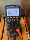
16 & 40 mV.
Last edited:


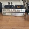


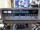
Xenon-Codex
Active Member
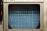
Rotel RX-820 had partially faulty transistor 2SB507. Sine wave looked like this, and the bias adjustment was at 0 at every position. Still worked with distorted sound, other channel was normal. With new BC243 and BC244's it gives clean sine wave.

melofelo
Addicted Member
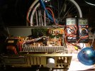
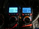
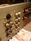
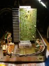
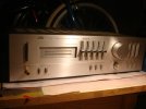
An unrestored JVC AX-2. Been sitting in the cupboard for about 10 years.. needed the volume pots and selector switches cleaning..some Brasso on the phono jacks followed by a wipe with IPA to remove tarnishing brought them back to shiny. The speaker relay was acting up as the right channel kept dropping out sometimes when i switched it on. Then when I tapped it with both channels playing the soudn dropped out on the right channel again , so I figured either the relay contacts needed cleaning or the solder joints were not making a good contact. Reflowed them from the other side anyway as I noticed that lifting one side of the amp with the cover off made the board flex ever so slightly and the right channel dropped out again. Anyway..I've not got much electronic experience to service this amp..but it still sounds pretty good once i reflowed the solder to the relay. Then I remembered this thread and decided to check the dc offset after letting it warm up and idle for about 30 minutes. I'm assuming these figures are ok ? Just breathing on it with the case open causes the dc offset to drop a couple of mv temporarily...but the steady readings look like this.
Attachments

Last edited:
I think this is a hard to find replacement relay for this pin configuration. There are adapters made. Google the relay P/N and you will find several solutions. I have had luck cleaning the contacts with contact cleaner on a strip of paper and carefully pulling it through the contacts. Measure the resistance before and after of the closed contacts and you will see the results!The speaker relay was acting up.....
melofelo
Addicted Member
Thanks for your reply. So far the relay seems ok now that the pins have been resoldered. I'll pull it if it plays up again and clean the contacts inside. It's a Nice little amp btw.I think this is a hard to find replacement relay for this pin configuration. There are adapters made. Google the relay P/N and you will find several solutions. I have had luck cleaning the contacts with contact cleaner on a strip of paper and carefully pulling it through the contacts. Measure the resistance before and after of the closed contacts and you will see the results!
Hello
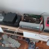
I have a problem with unstable offset in Kenwood Ka 1000 Sigma Drive, on cold start about 100 ~ 140 Mv after 10 minutes it shifts in the range of -30 ~ 30 Mv in both channels, the differential pairs were replaced with the same 2SC535 with no effect, transistors Q35, Q37, Q36 , Q38 (2sa912) changed to KSA1142Y with additional radiator cooling and Q39, Q40 (2SC1885S) changed to KSC2690A-Y, offset potentiometers were also replaced, entire bottom plate received new solders. What could be the problem with this behavior of the amplifier? Could the fact that it is 220V (currently 240V) be a problem in the power supply section? the main capacitors are 63V, does that have anything to do with it?
I have a problem with unstable offset in Kenwood Ka 1000 Sigma Drive, on cold start about 100 ~ 140 Mv after 10 minutes it shifts in the range of -30 ~ 30 Mv in both channels, the differential pairs were replaced with the same 2SC535 with no effect, transistors Q35, Q37, Q36 , Q38 (2sa912) changed to KSA1142Y with additional radiator cooling and Q39, Q40 (2SC1885S) changed to KSC2690A-Y, offset potentiometers were also replaced, entire bottom plate received new solders. What could be the problem with this behavior of the amplifier? Could the fact that it is 220V (currently 240V) be a problem in the power supply section? the main capacitors are 63V, does that have anything to do with it?
Last edited:

oldNslo
Member
Wow, 257 pages, after a quick glimpse through, it was lots of questions and lots of readings.
Aiwa (new to me) - L= 5.0, R=20.6
JVC (50 years in the stable) L=23.3, R=23.4
Question, with the guidance of "volume at minimum" should we define that as a "comfortable" listening level and not set to "off"? It seems volume does not impact my readings when testing.
Q#2, should I be surprised that I can't seem to find a DC offset spec in my JVC Service manual?
Aiwa (new to me) - L= 5.0, R=20.6
JVC (50 years in the stable) L=23.3, R=23.4
Question, with the guidance of "volume at minimum" should we define that as a "comfortable" listening level and not set to "off"? It seems volume does not impact my readings when testing.
Q#2, should I be surprised that I can't seem to find a DC offset spec in my JVC Service manual?
Last edited:
All original SX650 that had the flickering light issue (took the power switch apart and cleaned it, which appeared to fix the problem...for now). Still has some intermittent channel issues, but hoping another round of deoxit / lubricant will take care of it. DC offset appears to be ok:
Left Channel: ~23mV
Right Channel: ~24mV
Left Channel: ~23mV
Right Channel: ~24mV

justin_r_23
Active Member
Concept 2.5 ca 1979, unknown service history:
R: 30mv
L: 15mv
R: 30mv
L: 15mv

cheapo_eddy
Active Member
Thanks for the nostalgic reminder of my youth spent at the repair bench, poring over burnt resistors, carbonized traces, fuses heavily derated with aluminum foil and outputs shorted so hard it made the lights go dim when you flipped the power on. "There is no such thing as a minor driver board fire."Time for one of those long, boring semi-technical posts that no one here reads...
As a few of you know, I bought a rare Kenwood 700M amplifier a few weeks ago on eBay. It arrived with a weak channel which was taken care of by replacing a bypass cap. Since then, I have gone through the entire amp and replaced all the electrolytic capacitors with the exception of the big power supply caps (not that expensive...maybe $20 in caps).
The previous owner described the amp as 'perfect' sounding, and compared with the big Mac's and Krell's and such. Before buying it, he described his current system which was quite high-end. I assumed that since he owned expensive equipment that he knew what he was listening to.
:withstpd:
Got the amp back together today (parts finally in), and fired it up with my small Dynaudio's (can't use the Heil/Dynaudio's for this, as they are bi-amped). Ummm...it sounded like ass. OK, it didn't always sound like ass, but at low volume levels it was obvious that something was wrong. I had a pretty good idea what was going on, so I grabbed my meter. Sure enough, there was 100mV of DC offset in the left channel, and almost 250mV (!!!) in the right! 250mV is almost enough for the protection circuitry to kick in!! Not good. I pulled the driver boards out and replaced the amp input differential pairs for both channels with new Zetex HG PNP's ($5 in transistors, no biggie). DC offset is now about 12mV in both channels. An input pair being as unbalanced as the Kenwood was when it arrived probably generates 10x the distortion as a properly balanced pair, especially at low volume. If you would like to read more about the benefits of a balanced differential pair, read here.
OK, sit down for another listen. NOW we're cookin'!! Amazing night and day difference. I can honestly say that it is without a doubt the nicest amp I have ever listened to, and there have been more than a few that impressed me. The bottom end on this thing is as clear as spring water, and it has an openess that is difficult to describe. As for power, my dummy loads cannot take the power output of this thing, but I can crank it for 10-15 seconds without destroying them. Left channel - 218W before clip, right channel - 220W, this into 8-ohms. Totally cool!! I just have never heard bass like this...wow...
Bottom line...if you expect to hear great sound, you just might...regardless of the reality. The guy I bought this from was well-meaning, but did not know how to listen subjectively. His new spendy amps could be performing horribly, and his expectations of what he felt he was supposed to hear would rule out anything to the contrary.
Your own subjectivity could be suffering too, so give yourself a reality-check.
As a semi-poll, I'd like to see those on this board whip out their multimeters and take a look at the DC that is being presented to the speakers. This means..
1. Speakers disconnected (or connect the meter to the 'B' speakers and set the front panel speaker control accordingly)
2. Input set to an unusued position (not Phono)
3. Volume control at minimum.
4. Balance in center
5. Tone controls either defeated or set to mid position
6. Set your meter to read DC, and set to a low scale (300mV scale is common) Connect directly to the Pos and Neg of the speaker terminals
7. Give the amp 10 minutes to settle. Report back...I'd like to see how healthy all these old amps are.
If you read:
0 - 15mV: Damn good!! If you read '0V', you may have a capacitor output, or your meter is set wrong
16mV - 50mV: An acceptable value, especially at the lower end of this range. 2nd harmonic distortion is probably twice to four times what manufacturer's spec calls for at higher frequencies. Probably not audible, as the distortion is mostly in the upper octaves. At the upper end of this range I begin to raise an eyebrow. :saywhat:
50 - 85mV: Something is certainly amiss, and while this is not enough to put your speakers or equipment in jeopardy, the amp is running nowhere near where it should. I'd venture to guess that most of the DC-coupled amps that are in use by forum members here fall into this range.
100mV to ?: A high enough voltage will cause the DC protection to kick in. This happens at a level determined by the designer, but is usually equivalent to about a diode drop (600mV)or so. Needless to say, if you are listening to an amp with 100mV or more of DC offset, you have no idea what the amp really is supposed to sound like. Indeed, some amps without a differential input are actually designed to have a bit of DC at the outputs, but this is triple-rare, and I don't think anyone here owns one. (in my book it's piss-poor design, but if you can sell it WTH..)
Soooooo...go grab a meter and tell me what you find...

jd3rdcoast
Super Member
Q#1: Volume at minimum means just that. No Volume.Wow, 257 pages, after a quick glimpse through, it was lots of questions and lots of readings.
Aiwa (new to me) - L= 5.0, R=20.6
JVC (50 years in the stable) L=23.3, R=23.4
Question, with the guidance of "volume at minimum" should we define that as a "comfortable" listening level and not set to "off"? It seems volume does not impact my readings when testing.
Q#2, should I be surprised that I can't seem to find a DC offset spec in my JVC Service manual?
Q#2: Some amplifiers by design do not have a DC Offset adjustment. They are balanced by the circuit design. Typically, if there is creep in DC then the differential amplifier pairs have drifted in gain matching and should be replaced with gain matched sets of comparable replacement devices.

PoCko
New Member
Greetings to all!
I have a Denon integrated and I noticed on idle or full steam one of the power amplifier heatsinks is noticeably warmer than the other. So I begin by disconnecting all of the wires from the amp, volume to 0, cd as an input and tone defeat ON. Let it cool down for 4h and check the idle current after 10min mark at ON(the amplifier has only this adjustment pot). Left one was a little lower (11mV) but the right one was a little higher (13.5mV). It was very hard to adjust the left one. It drifts too quickly and it's not so stable. So I've only tinkered with that side for now and managed to set it up to 12mV. So I've decided to leave the right one untouched. That way after 60min on time it balanced out to stable L-11.6mV/R-11.5mV. The thing is that now after some testing the right heatsink still heats up more.
So I have a couple of questions on the subject which I'm not sure I understand correctly:
1. Is it normal for the idle current to drift a little constantly (+/-0.1)?
2. The manual states " setup after 2min ON time to 12mV, and after 10min to 12mV ''. So I don't have to bother afterwards if it fluctuates outside 12mV? Or I have to measure again after lets say 60 min ON time? I came to notice that the current stabilizes after about 45min+......
3. Do I have to set up the L and R side to be at 12mV on the 10 min mark or after 60min?
4. The tolerance for setting up is 0.5mV. If I get it set up to L - 11.5mV and R - 12.5mV is that good?
Any advice will be appreciated!
I have a Denon integrated and I noticed on idle or full steam one of the power amplifier heatsinks is noticeably warmer than the other. So I begin by disconnecting all of the wires from the amp, volume to 0, cd as an input and tone defeat ON. Let it cool down for 4h and check the idle current after 10min mark at ON(the amplifier has only this adjustment pot). Left one was a little lower (11mV) but the right one was a little higher (13.5mV). It was very hard to adjust the left one. It drifts too quickly and it's not so stable. So I've only tinkered with that side for now and managed to set it up to 12mV. So I've decided to leave the right one untouched. That way after 60min on time it balanced out to stable L-11.6mV/R-11.5mV. The thing is that now after some testing the right heatsink still heats up more.
So I have a couple of questions on the subject which I'm not sure I understand correctly:
1. Is it normal for the idle current to drift a little constantly (+/-0.1)?
2. The manual states " setup after 2min ON time to 12mV, and after 10min to 12mV ''. So I don't have to bother afterwards if it fluctuates outside 12mV? Or I have to measure again after lets say 60 min ON time? I came to notice that the current stabilizes after about 45min+......
3. Do I have to set up the L and R side to be at 12mV on the 10 min mark or after 60min?
4. The tolerance for setting up is 0.5mV. If I get it set up to L - 11.5mV and R - 12.5mV is that good?
Any advice will be appreciated!
Thank You in advance for the valuable input!
I have a few different problems and I am a newb, so please be patient with me.
First of all, I have a SONY STR-DB 798 receiver which unfortunately damaged 2 pairs of CANTON speakers( LE109 and GLE470). I don't understand why. On LE109 the tweeter is dead and one of the two low frequency speakers is damaged( distorts at higher volume and when pushed by hand makes a sound like paper being scratched). The GLE470 has the same damage to the speaker at the top. It sounds like something is rubbing against paper. both speakers got damaged on the same channel(FR) on high volume >+4DB
I tested the DC output on different outputs(SACD/CD, MDR/TAPE, VIDEO1, etc). Test was done at 00 DB. Test was done both with or without speakers connected. readings are the same.
It measures
- 12mV on FL and 4mV on FR after 2 min
- 21mV on FL and 12mV on FR after 15 min
I measured impedance(dont know if it is correct) and it returned 88 Ohms on FL and 49 on FR.
If I interpret corectly, the service manual says 15+-2mV(BIAS adjustement) and 50Ohms for analog. FR seems almost spot on.
PS. This receiver was not used for 7-8 years because in went into PROTECT mode. The issue was intermitent, I went with it at SONY service, but they didnt find any solution. Since my son bought the GLE470s(a yera ago) the issue didnt reappear.
Second problem is a Pioneer VSX826 which I bought because SONY went into protect mode.
With this one which drives the LE109s, the problem is a general loss of volume except for the surround channels. The FL channel also doesnt emit medium frequencies at all. I used a signal generator and the FR was OK outputing the exact frequencies generated, but the FL didnt output anything.
The readings are as follows:
- FL 24mV
- FR 41mV
- C 25mV
- SBL 25mV
- SBR 25mV
service manual(for 821model because Icouldnt find the manual for 826) is giving a value of 2+-0.2mV
I have a few different problems and I am a newb, so please be patient with me.
First of all, I have a SONY STR-DB 798 receiver which unfortunately damaged 2 pairs of CANTON speakers( LE109 and GLE470). I don't understand why. On LE109 the tweeter is dead and one of the two low frequency speakers is damaged( distorts at higher volume and when pushed by hand makes a sound like paper being scratched). The GLE470 has the same damage to the speaker at the top. It sounds like something is rubbing against paper. both speakers got damaged on the same channel(FR) on high volume >+4DB
I tested the DC output on different outputs(SACD/CD, MDR/TAPE, VIDEO1, etc). Test was done at 00 DB. Test was done both with or without speakers connected. readings are the same.
It measures
- 12mV on FL and 4mV on FR after 2 min
- 21mV on FL and 12mV on FR after 15 min
I measured impedance(dont know if it is correct) and it returned 88 Ohms on FL and 49 on FR.
If I interpret corectly, the service manual says 15+-2mV(BIAS adjustement) and 50Ohms for analog. FR seems almost spot on.
PS. This receiver was not used for 7-8 years because in went into PROTECT mode. The issue was intermitent, I went with it at SONY service, but they didnt find any solution. Since my son bought the GLE470s(a yera ago) the issue didnt reappear.
Second problem is a Pioneer VSX826 which I bought because SONY went into protect mode.
With this one which drives the LE109s, the problem is a general loss of volume except for the surround channels. The FL channel also doesnt emit medium frequencies at all. I used a signal generator and the FR was OK outputing the exact frequencies generated, but the FL didnt output anything.
The readings are as follows:
- FL 24mV
- FR 41mV
- C 25mV
- SBL 25mV
- SBR 25mV
service manual(for 821model because Icouldnt find the manual for 826) is giving a value of 2+-0.2mV