• The move to the new server is done. There are some software and database maintenance updates in process. This has us passing the hat around to help out. We appreciate any donations. Seriously, even a dollar helps. The payment page may be found here - https://www.audiokarma.org/support.html

Amplifier Distortion, DC-Offset, and You!

Greetings to all!

I have a Denon integrated and I noticed on idle or full steam one of the power amplifier heatsinks is noticeably warmer than the other. So I begin by disconnecting all of the wires from the amp, volume to 0, cd as an input and tone defeat ON. Let it cool down for 4h and check the idle current after 10min mark at ON(the amplifier has only this adjustment pot). Left one was a little lower (11mV) but the right one was a little higher (13.5mV). It was very hard to adjust the left one. It drifts too quickly and it's not so stable. So I've only tinkered with that side for now and managed to set it up to 12mV. So I've decided to leave the right one untouched. That way after 60min on time it balanced out to stable L-11.6mV/R-11.5mV. The thing is that now after some testing the right heatsink still heats up more.

So I have a couple of questions on the subject which I'm not sure I understand correctly:

1. Is it normal for the idle current to drift a little constantly (+/-0.1)?

2. The manual states " setup after 2min ON time to 12mV, and after 10min to 12mV ''. So I don't have to bother afterwards if it fluctuates outside 12mV? Or I have to measure again after lets say 60 min ON time? I came to notice that the current stabilizes after about 45min+......

3. Do I have to set up the L and R side to be at 12mV on the 10 min mark or after 60min?

4. The tolerance for setting up is 0.5mV. If I get it set up to L - 11.5mV and R - 12.5mV is that good?


Any advice will be appreciated!

This thread is for people to learn about and report on dc offset (as measured at speaker terminals of amp/receiver).

I suggest that you repost your questions in the Solid State subforum. You will likely get more responses about your idle current setting questions there.
 
Thank You in advance for the valuable input!

I have a few different problems and I am a newb, so please be patient with me.
First of all, I have a SONY STR-DB 798 receiver which unfortunately damaged 2 pairs of CANTON speakers( LE109 and GLE470). I don't understand why. On LE109 the tweeter is dead and one of the two low frequency speakers is damaged( distorts at higher volume and when pushed by hand makes a sound like paper being scratched). The GLE470 has the same damage to the speaker at the top. It sounds like something is rubbing against paper. both speakers got damaged on the same channel(FR) on high volume >+4DB
I tested the DC output on different outputs(SACD/CD, MDR/TAPE, VIDEO1, etc). Test was done at 00 DB. Test was done both with or without speakers connected. readings are the same.
It measures
- 12mV on FL and 4mV on FR after 2 min
- 21mV on FL and 12mV on FR after 15 min
I measured impedance(dont know if it is correct) and it returned 88 Ohms on FL and 49 on FR.
If I interpret corectly, the service manual says 15+-2mV(BIAS adjustement) and 50Ohms for analog. FR seems almost spot on.
PS. This receiver was not used for 7-8 years because in went into PROTECT mode. The issue was intermitent, I went with it at SONY service, but they didnt find any solution. Since my son bought the GLE470s(a yera ago) the issue didnt reappear.


Second problem is a Pioneer VSX826 which I bought because SONY went into protect mode.
With this one which drives the LE109s, the problem is a general loss of volume except for the surround channels. The FL channel also doesnt emit medium frequencies at all. I used a signal generator and the FR was OK outputing the exact frequencies generated, but the FL didnt output anything.
The readings are as follows:
- FL 24mV
- FR 41mV
- C 25mV
- SBL 25mV
- SBR 25mV
service manual(for 821model because Icouldnt find the manual for 826) is giving a value of 2+-0.2mV
This thread is for people to learn about and report on dc offset (as measured at speaker terminals of amp/receiver). Your dc offset measurements are within limits.

As for your other questions, I suggest that you repost your questions in the Solid State subforum. You will likely get more responses there. If you are blowing tweeters, you are overdriving them, particularly since you identify woofer problems. The best place to troubleshoot that problem is in the Solid State Forum. I would make separate posts, one for each of your receivers, because the problems are different.
 
Just went through a receiver that had about 160mv on both channels. Took some distortion readings at various output levels before swapping in new differential transistors that were matched on one of them cheapo transistor testers. Now have 30mv and 60mv offset but distortion readings have been reduced in half. From .12% down to .05% and .08% down to .04% at higher output. Everything else is is still original in the early 70's receiver, sounds nice, now deciding on if I will dig into a multiplex issue with it.
 
I just checked my Kenwood / Trio L-05M mono-blocs. I changed out all the caps around 2011 and some other stuff, including Bournes pots for dialing in DC offset:
Left amp = mV5; Right amp mV1.
Darn solid old trucks these amps! I never managed to get the board looking clean and nice, but they work well. These are Japanese Trio versions in dark green hoods running on 100 VAC, 50/60 Herz.
 
Have a Claricon 36-350. From what I gather it’s an early 70’s Japanese receiver. There is a small cloth tag attached to the power cord with a very stern warning not to power on the unit without having speakers attached and ensuring that the leads are not shorted. Is this a concern with regard to running this test? The left channel is muffled and distorts except at very low volumes, and has a barely noticeable hum that is unaffected by volume or balance setting. Right channel sounds pretty good.
 
Have a Claricon 36-350. From what I gather it’s an early 70’s Japanese receiver. There is a small cloth tag attached to the power cord with a very stern warning not to power on the unit without having speakers attached and ensuring that the leads are not shorted. Is this a concern with regard to running this test? The left channel is muffled and distorts except at very low volumes, and has a barely noticeable hum that is unaffected by volume or balance setting. Right channel sounds pretty good.
It should not be tested with the output volume set at zero. You will be testing with a voltage meter between the +
/ - on your speaker terminals, with the volume at zero. Left and right. Should not present a problem. The speakers should not be attached to the terminals or else you won’t get an accurate reading.

Don’t think it would be an issue turning on your amp but you could turn it on with the speakers attached, then disconnect them w volume at zero. Test and be done. I don’t know if you can hurt it if the volume is zero and no speakers attached, but shorted out speaker wires will definitely hurt it.
 
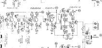
Actually found a schematic for it. Certainly don't want to short the speaker outputs, but there would be no problem operating them open circuit. Interesting that the output stage has no temperature compensation on the bias. And since the outputs are capacitively coupled, the output offset voltage would be meaningless any way.
Screenshot 2024-04-21 161121.jpeg
 
Actually found a schematic for it. Certainly don't want to short the speaker outputs, but there would be no problem operating them open circuit. Interesting that the output stage has no temperature compensation on the bias. And since the outputs are capacitively coupled, the output offset voltage would be meaningless any way.
View attachment 3182887
Certainly hope it’s meaningless. Got 143mV on the left, and 145mV on the right.
 
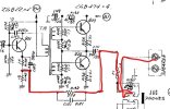
Yes, you are seeing the bias current from Q21 dropped across R140. Tells me Q21 is drawing 10mA which seems reasonable.
Screenshot 2024-04-22 130129.jpeg
 
I just finished installing some new filter caps in my Hitachi HA-610 and figured I should take some readings at the terminals. The results were:
L 40.8mv R 60.1mv

So, trying my best to follow the service manual, I took reading off resistor 725 to the chassis and got 48.8v - which is above what the service manual recommends in setting idle current

I really don't want to just go and randomly turn the potentiometer(s) in the hopes the value will drop and, at least for me, the service manual is not nearly as detailed as others I've seen.
Any suggestions or guidance is extremely welcomed and thank you in advance1000010137.png1000010135.png1000009935.jpg
 
I just finished installing some new filter caps in my Hitachi HA-610 and figured I should take some readings at the terminals. The results were:
L 40.8mv R 60.1mv

So, trying my best to follow the service manual, I took reading off resistor 725 to the chassis and got 48.8v - which is above what the service manual recommends in setting idle current

I really don't want to just go and randomly turn the potentiometer(s) in the hopes the value will drop and, at least for me, the service manual is not nearly as detailed as others I've seen.
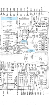
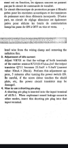
Any suggestions or guidance is extremely welcomed and thank you in advanceView attachment 3185804View attachment 3185806View attachment 3185816
The manual describes adjusting idle current, which is something different than and unrelated to dc offset voltage. If you measured 48.8 V across the idle resistor and not 48.8 mV, then you have serious problems with your unit. If it is indeed 48.8 mV across the resistor, they you should adjust the VR as described in the manual.

This thread is for learning about dc-offset and for people to record what they are finding on their equipment. This thread is not for fixing high dc-offset.

I suggest that you create a new post in the Solid State sub-forum for advice on how to work on your Hitachi.
 
I just finished installing some new filter caps in my Hitachi HA-610 and figured I should take some readings at the terminals. The results were:
L 40.8mv R 60.1mv

So, trying my best to follow the service manual, I took reading off resistor 725 to the chassis and got 48.8v - which is above what the service manual recommends in setting idle current
Measure **across* the resistor, not from each leg to ground.
 
Recent acquired this very nice Linn LK280 amp. DC offset readings are :

R -53.5mV
L -3.4mV

It's very consistent, even after extensive warm-up. Actually consistent for a very long time - the previous owner was getting L 11.5mV / R 33.3mV at least a year ago. In fact, a Stereophile review amp measured L 27.9mV / R 10mV way back in 2008. So I'm guessing its a mismatch in the input differential transistors and not unusual. Regardless, the amp sounds great, but if I can get that right channel closer to 0, the amp is worth the effort.

I'm gonna post up a schematic in a new thread and see if someone can help me positively identify the exact pair of transistors to replace. I've already got a Mouser order of 20 each to try and find a close match.....
 
Last edited:
Back
Top Bottom