• The move to the new server is done. There are some software and database maintenance updates in process. This has us passing the hat around to help out. We appreciate any donations. Seriously, even a dollar helps. The payment page may be found here - https://www.audiokarma.org/support.html

Another AU-20000 Restoration

Will_Emanuel

AK Subscriber
Subscriber
Hello all,
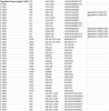
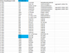
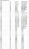
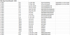
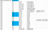
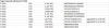
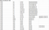
The time is come for me to document a complete restoration I recently finished on an AU-20000. I first want to thank @mattsd for his restoration thread, as I used that as a baseline when starting this restoration. I was unable to find a single complete BOM for the unit on AK, so I went ahead and took the time to write one up in hopes that others find it useful. I noted all the parts I replaced on each board, with their designators, original values, and replacement part numbers for easy ordering on Mouser/DigiKey. I also left some notes for parts where the values may have been changed, these I followed from Matt's restoration. I also noted if I found different parts than stated in the service manual. The complete BOM is attached below.
 
Register to hide this ad
Ok, lets begin.
uHvrk8W.jpeg


7rtYJAO.jpeg


NHsGxye.jpeg


bN6cXtm.jpeg


dhzWigx.jpeg


The unit came in in pretty good physical condition. Opening it up revealed some work done by a previous tech on the power supply and amplifier driver cards. I also found a counterfeit replacement Toshiba output transistor on one channel, as shown below.

q2ePWvo.jpeg


Pulling out the Driver cards and power supply, I found that only a few capacitors on each boards were replaced, and everything else was left original. The caps were held in with hot glue and the original corrosive glue was not removed underneath.

nb86s0R.jpeg


78v72jn.jpeg


I also noticed that two larger caps on the F-2512 Connector board were replaced and glued into place, as shown below.

BvG2pEB.jpeg
 
The first order of business was to remove the new caps previously installed on the power supply and driver cards and remove all the corrosive glue.

22yhP1R.jpeg


cDmbmxX.jpeg


I now turned my attention first to the F-2508 Regulated Power Supply Board. The parts used for this board are as follows. All of this information for each of the boards documented can be found in the complete BOM as attached at the top of this thread.
upload_2022-4-9_11-47-31.png

Here are the after Photos of the Power supply board.

omsem31.jpeg


maxIe3r.jpeg
 
Next up was the two F-2507 Driver Cards. The parts used for each of these boards are as follows.

upload_2022-4-9_11-50-47.png

Here is an after photo of one of the completed F-2507 Driver cards.

B77dtnE.jpeg


The F-2512 Connector board was next, just four electrolytics to replace here.

upload_2022-4-9_11-52-35.png

6SO8FwW.jpeg


After this was the Monstrous F-2511 Protection board. First, its time to fish it out.

yMGpkoF.jpeg


3rEEn6c.jpeg


ZkYKUNY.jpeg


This was a pretty intensive board to do, lots of parts to be replaced. The parts used are as follows
upload_2022-4-9_11-57-1.png

and here we are, much better.

wLJ95ka.jpeg
 
Next up was the two large filter caps. The Nippon Chemi-Con replacements I used were nearly a direct fit, I only needed to widen the washers and ground bus bar to allow for the larger screws on the replacement caps.

w6yWdzh.jpeg


U2zEaBC.jpeg


I pulled the output transistors and their heatsinks at this point to allow more space to install the new caps easily.

RaxS9bQ.jpeg


These new caps are about as big as you can manage in this chassis.

Next up was the output transistors and output boards.

lC6VmZK.jpeg


Besides the one counterfeit replacement transistor, the other original Toshiba 2SB554 and 2SD424 outputs measured very poorly, with some measuring hFEs of 3 and 7. These were replaced with MJ21193/MJ21194s. The 93/94 were out of stock when I ordered parts, so I chose the nearly identical MJ21195/MJ21196 instead, which worked perfectly.

ZnW9t4S.jpeg


Separating the heatsinks allows us to take a better look at the output boards. These boards have quite a few vias that connect the top and bottom layers of the board that are notorious for causing issues with the amp. These can be located by finding the many pads with circles around them on the board. Each of these were reflowed and checked with a meter for solid continuity before continuing.

This next step is completely unnecessary, but I like to thoroughly clean the output heatsinks before installing new output transistors. To the sink they go for a solid cleaning.

5VfR77L.jpeg


6LUyjzC.jpeg


Much better.

Once the heatsinks were cleaned and the output boards were reflowed, new output transistors were installed with new micas and fresh thermal compound.

XyjMsP4.jpeg


TrrsZmT.jpeg


17OtUmk.jpeg


nhMY7LG.jpeg


The reassembled output assemblies were then reinstalled in the unit.

ZszQJJV.jpeg


Once this was done, I went ahead and installed the driver boards and power supply to confirm operation of the power supply, protection circuit, and amplifier sections as well as amplifier calibration.

R6s8UvQ.jpeg


vfa3OKz.jpeg


All tested out beautifully, with both amp channels being set to their desired 35mV of idle current and 0mV of DC offset.
 
With the amp section finished, it was time to dig into the preamplifier section. I love just how modular the AU-20000 is, such a treat to work on. the entire preamp assembly swings right out with a few screws removed.

YCXaObu.jpeg


First up was the F-2495 Tone Amp board.

pGWDLUu.jpeg


The parts list used for this board is as follows.

upload_2022-4-9_12-16-19.png

Here is the completed F-2495 board.

HyW9pMP.jpeg


After this was the F-2505 Flat Amp Board

hSkInDG.jpeg


The parts used for the F-2505 were as follows

upload_2022-4-9_12-19-16.png

Here is the finished F-2505

YoOV7yr.jpeg


The F-2501 Equalizer Amp board was up next

3riPvLC.jpeg


Here are the parts used for the F-2501.

upload_2022-4-9_12-21-53.png

And here is the after. NOTE TR11 and TR12 are reversed in this photo, they were later fixed before the F-2501 was installed in the unit.

XyeHGSA.jpeg
 
The F-2504 Filter Circuit board and its two F-2498 Filter Amp board were up next.

The parts list for the F-2504 is as follows.

upload_2022-4-9_12-24-56.png

The parts for each F-2498 are also below.

upload_2022-4-9_12-25-31.png

Here is a finished F-2498 Board

7794Pio.jpeg


Here is both F-2498s mounted back on the completed F-2504.

LYsIYGv.jpeg


The F-2503 Tape Copy board was up next. The parts used for it are attached below.

upload_2022-4-9_12-27-27.png

here is the finished F-2503.

X9KUI62.jpeg


Last up was the F-2496 Meter Board

vatTv9X.jpeg


The parts list for the F-2496 is as follows.

upload_2022-4-9_12-29-4.png

I forgot to snag a photo of the finished F-2496, but all the parts listed above were used for the rebuild.

After this, it was time for some testing and reassembly.

03AnAze.jpeg


JfP9845.jpeg


And here we are. Quite a difference compared to when it first arrived on the bench. Now time to throw the covers on and take it upstairs for some more serious listening.

SiNJapc.jpeg


Thought I'd throw this in, here's everything that was replaced.

SrFoWsc.jpeg
 
Finally upstairs for testing. Stacked next to its little brother, the AU-11000. That 11000 I have already restored, it has had a pretty rough life, went through quite a few inexperienced techs before myself. But enough about the 11k, how does the AU-20000 sound after the rebuild? Wow. I was quite impressed. It wasn't even comparable to the 11k, much more headroom and heft in the low end, as expected with the significant increase in power output. It certainly has that warm Sansui house sound, while also being very detailed. The noise floor dropped significantly after the rebuild, I suspect all those 2SA726s in the preamp were part of that problem. This is certainly my all time favorite Sansui that I've heard. Now, time for some glamour shots.

twI0kSp.jpeg


LW6xTIL.jpeg


mIwlhNK.jpeg


qLB8FVh.jpeg


2TAcIJv.jpeg


ipue15N.jpeg
 
That's excellent! - one thing I do take issue with.

You say this...
This next step is completely unnecessary, but I like to thoroughly clean the output heatsinks before installing new output transistors. To the sink they go for a solid cleaning.
I think it is absolutely necessary and worthwhile, nice clean heatsinks work better because of better airflow. ;)

You should see some of the furry heatsinks I've dealt with :)
 
That's excellent! - one thing I do take issue with.

You say this...
I think it is absolutely necessary and worthwhile, nice clean heatsinks work better because of better airflow. ;)

You should see some of the furry heatsinks I've dealt with :)

Haha, glad to hear I’m not alone there! Everything Must be clean for me, worth the effort to do as much as you can while the unit is apart.
 
Next up was the two F-2507 Driver Cards. The parts used for each of these boards are as follows.

View attachment 2535144

Here is an after photo of one of the completed F-2507 Driver cards.

B77dtnE.jpeg


The F-2512 Connector board was next, just four electrolytics to replace here.

View attachment 2535147

6SO8FwW.jpeg


After this was the Monstrous F-2511 Protection board. First, its time to fish it out.

yMGpkoF.jpeg


3rEEn6c.jpeg


ZkYKUNY.jpeg


This was a pretty intensive board to do, lots of parts to be replaced. The parts used are as follows
View attachment 2535150

and here we are, much better.

wLJ95ka.jpeg
I would bump up the bleeder resistors to 5W, I always seen them very toasty. But otherwise great job, very very clean, I'm impressed.
 
Will - as always, terrific work.
My only change would be to add fuses on the power feeds to the output transistors. On mine I used 7.5 amp ATC fuses.
 
Last edited:
This is quite the difference from the horrible looking engineering designs from Marantz and Pioneer I see here in the other mod/rebuild threads. The Sansui has a workable layout scheme, toroidal transformers, modular construction and as easy as it looks to work on they probably performed for years without needing servicing.

What year is it from?

The 35mv bias seems excessive. Does the unit get very hot under normal operation? If not can you tell me why the bias needs to be set that high?

Nice (sensible) work!
 
This is quite the difference from the horrible looking engineering designs from Marantz and Pioneer I see here in the other mod/rebuild threads. The Sansui has a workable layout scheme, toroidal transformers, modular construction and as easy as it looks to work on they probably performed for years without needing servicing.

What year is it from?

The 35mv bias seems excessive. Does the unit get very hot under normal operation? If not can you tell me why the bias needs to be set that high?

Nice (sensible) work!
Believe it or not, the unit runs quite cool despite that bias, it actually isn't very high at all given that is spread across all 6 output transistors on each channel. This unit dates from 1975. The design sure does make it quite easy to work on.
 
Beautiful work and thanks for sharing the board-by-board process as well as all the BOMs! I'd love to have an AU-20000, but I'm satisfied having an AU-9900. Once in a while I've seen an AU-11000 come up for sale within a 3 hour drive, but never see an AU-20000. The Definition/Professional series are the best looking Sansuis, IMHO.
 
Back
Top Bottom