• The move to the new server is done. There are some software and database maintenance updates in process. This has us passing the hat around to help out. We appreciate any donations. Seriously, even a dollar helps. The payment page may be found here - https://www.audiokarma.org/support.html

Another AU-919

I've started climbing a very steep learning curve regarding audio-electronics... but I keep slipping back down as I don't have the mental capacity to retain what I learn. However I still enjoy reading on the subject, on AK and elsewhere.

I found the following to be interesting and educational: http://www.qrxrestore.com/electrolytic-reliability/. It has helped me understand why amplifiers need re-capping (and re-setting) as they age, and why I should have got my AU-919 seen to long before now. I can't wait to give it a spin post-overhaul!
 
Am I right in thinking that Jump bypasses the main amp, so that the feed to the speakers is supplied only by the pre-amp stage? That was my thinking, right or wrong.

Almost... engaging the Jump Switch removes part of the amplification circuitry that feeds the driver board, hence the big drop in volume and the need to turn the volume control up to restore the same sound level. The idea behind this is that 'less is more' - in other words less circuitry for the signal to pass through = less distortion or less colouration, and therefore a 'cleaner' signal appearing at the speakers. This idea was re-invented with the 'Direct' switches of later models in the Sansui line, like the AU-X701, and it does (to my ears) make an audible difference for the better. The amplifier is so good anyway that you have to be listening pretty carefully, and be familiar with the sound of that amplifier, to easily notice this effect.

After safeguarding the Output Transistors by reconditioning the Driver Board - and probably the PSU's as well, I will investigate the problem you describe. ;)

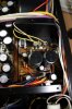
I don't want to change any components on the Flat Amp until I have investigated your report, as the disturbance to components might just 'bury' the problem only for it to re-appear when you have it back again - and I am not going to allow that to happen.
 
Last edited:
Thanks for the very clear explanation as to the circuitry bypassed with Jump. Thanks also for attending specifically to the Left channel distortion problem.

I can understand the quality of delivery being improved by using Jump, but my room acoustics and equipment setup need the tone controls that it disables. I'm very much looking forward to not needing to use Jump when you've worked your magic on the 919.
 
Last edited:
If it turns out like the other two I have worked on you are going to love it!
 
Last edited:
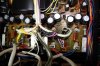
Ugh, pulling connector pins, so far the only unit I get in the habit of doing that to is the AU-717 power supply board. Best way I have found to really get at the over enthusiastic factory glue application specialist applicators without stressing the board. Now you got the parts should be fun to watch sir :)
-Lee
 
5h3iRSX.gif

giphy.gif
 
Last edited:
Is there anything that could be done to cause the resistors to run cooler?

Not really Moe, you have a certain voltage coming in, and on the far side of the resistor you have a 27V zener, the incoming voltage minus the zener voltage has to be dropped across the resistor with the zener current passing through it = a certain amount of heat generated. I did some temperature measurements on my own AU-919 in that area and I seem to remember seeing around a 10C temperature drop at C61 & C62 by doing 'my little trick' + I also mount the 27V zeners on ceramic beads to get them away from the PCB and in free air - it might not do much but every little helps, and it's easy to do.
 
Often you will find that the board you are working on will exhibit component heating around resistors that were flush mounted at the factory, it always is good practice to get those legs in the air 1/4' or so to allow full airflow. In the next episode John will show us how he always makes those perfect 90 degree bends on the resistor leads, after all who wants a chorus line of resistors with their legs going every which a ways j/k :)
Another AK member has found that super thin rc gas fuel line works a treat to protect the legs from shorting out, I need to pick some up as it also makes those original Sansui wire loom ties look original rather than zip ties.
 
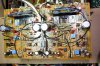
Driver board complete

IMG_2162a.jpg

And for you sharp eyed ones, when cleaning the board and checking my work (we all do that don't we ? :rolleyes: ) I discovered the missing 2 capacitors C53 & C54 and installed them. :)
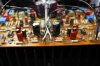

And the detail of that minor modification

IMG_2163a.jpg

You can see here that the heat flow from those two resistors (and the zeners) is no longer aiming directly at the two large electrolytic capacitors in the foreground. (the top of the board is nearest you in the picture).
 
Last edited:
Has not been turned on since the date of purchase...hence my interest...:lurk:

Well in that case you may find this:
http://www.audiokarma.org/forums/index.php?threads/new-addition-au-919.467393/

And this:
http://audiokarma.org/forums/index.php?threads/another-au-919-recon.605134/

Maybe of of interest.

Also 'AK search' will easily bring up a few more - There are excellent ones by leestereo, and scottrt.

BTW: latest is F-2844 almost complete, 8 components removed, heatsink removed, cleaned, new heatsink compound, components replaced, more cleaning. F-2845 starting tomorrow.
 
Last edited:
I searched for clip-on heat sinks that might help you dissipate the heat from the two large resistors, but did not find anything that looks like a safe solution. Have you considered leaving the leads long, mounting them high, and angled apart? Looks like you would have clearance.

You could mount the resistors high with a heat sink between them and figure out a secure way to clamp the heat sink between the two resistors. This sounds like a kluge, but it might help.
 
Hi Steve, they are mounted high, and with long leads, they aren't ferociously hot but they do quietly 'cook' the 2 zeners and those 2 electrolytics, I am happy the present solution is enough to deal with the issue. ;) (I did think of mounting the resistors on the print side of the board).

When I first noticed this on my own AU-919 I touched the electrolytic capacitors and they were 'hot' - no other word to describe it. Their lifespan at this temperature must have been very short.
 
Last edited:
Back
Top Bottom