

You are using an out of date browser. It may not display this or other websites correctly.
You should upgrade or use an alternative browser.
You should upgrade or use an alternative browser.
Another AU-919
- Thread starter Hyperion
- Start date
-
- Tags
- au-919 reconditioning





Multimode
Active Member
I wrote in my Introduction to AK that I'd lost some interest in listening to Hi Fi over recent years but was now 'rediscovering' it.
Whilst following John's restoration of the 919, and after reading the many other interesting and educational related postings on the forum, I've become convinced that my loss of interest was due to the sound quality from the amp having deteriorated gradually and unnoticed over my 36 years of ownership.
Where I used to play a record and concentrate on, say, the saxophone's rendition, then play it again and listen to the trumpet... etc, it had become just 'good music' hardly any better than my internet radio player was giving me.
Just as a carpenter's plane and chisels need re-sharpening now and then so as work properly, I'm now totally won over to the fact that amplifiers need recapping and re-setting from time to time so as to keep doing the job for which they were designed and purchased. It took me a while to discover this, and it came about through my visits to the AK forum. Thank you all !
Whilst following John's restoration of the 919, and after reading the many other interesting and educational related postings on the forum, I've become convinced that my loss of interest was due to the sound quality from the amp having deteriorated gradually and unnoticed over my 36 years of ownership.
Where I used to play a record and concentrate on, say, the saxophone's rendition, then play it again and listen to the trumpet... etc, it had become just 'good music' hardly any better than my internet radio player was giving me.
Just as a carpenter's plane and chisels need re-sharpening now and then so as work properly, I'm now totally won over to the fact that amplifiers need recapping and re-setting from time to time so as to keep doing the job for which they were designed and purchased. It took me a while to discover this, and it came about through my visits to the AK forum. Thank you all !

Well noted sir. For a real trip down memory lane stop by this thread in the general audio forum
Interesting Stereo Ads? Post a pic for memory lane's sake.
-Lee
Interesting Stereo Ads? Post a pic for memory lane's sake.
-Lee

Now the F-2835 - MM Head Amp Board.
Just removed a few electrolytic capacitors for a look at the glue - not nice.
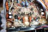
With my recently acquired Peak Component Tester, I have been measuring the Value and ESR of the vast majority of the electrolytic capacitors I am removing. Most show values very close to their marked value and with reasonable ESR. Some show high ESR (several times higher) compared to their new replacement, others show value reductions enough to cause concern. Four removed today show reductions of 35% in value compared to their marked value, these were all marked with the same value, and all right next to a hot heatsink. (seen at the bottom of the pic above).
Just removed a few electrolytic capacitors for a look at the glue - not nice.
With my recently acquired Peak Component Tester, I have been measuring the Value and ESR of the vast majority of the electrolytic capacitors I am removing. Most show values very close to their marked value and with reasonable ESR. Some show high ESR (several times higher) compared to their new replacement, others show value reductions enough to cause concern. Four removed today show reductions of 35% in value compared to their marked value, these were all marked with the same value, and all right next to a hot heatsink. (seen at the bottom of the pic above).
Last edited:

ghazzer
Senior Member
Gadzooks!! The component density on that board is over the top. Think they could have poured a few more resistors in there?
Perhaps the replacement caps will be slightly smaller than the originals and allow for a small increase in heat dissipation.
I've seen some very small 5vdc fans. Can these be sufficiently electrically isolated from the "signal components" that the do not distract from the signal quality? Seems that even a wee bit of air movement inside that case might help it last for another 36 years.
Nice work John, and I am enjoying the documentation.
Perhaps the replacement caps will be slightly smaller than the originals and allow for a small increase in heat dissipation.
I've seen some very small 5vdc fans. Can these be sufficiently electrically isolated from the "signal components" that the do not distract from the signal quality? Seems that even a wee bit of air movement inside that case might help it last for another 36 years.
Nice work John, and I am enjoying the documentation.
Multimode
Active Member
That's an interesting account of Values and ESR changes, and I am starting to understand the subject just a tiny bit... I think!
Am I correct in assuming that a bad connection to the board can increase the effective ESR of a capacitor? I'm thinking of the instance with the subject amp where a leg fell off a cap as it was being removed, which might suggest that a resistive connection existed prior to removal.
If I'm right - which will be a novelty in itself - the measured ESR could be good but the effective ESR would likely be very bad.
As before, please excuse a novice trying to discuss matters he doesn't really understand!
David.
Am I correct in assuming that a bad connection to the board can increase the effective ESR of a capacitor? I'm thinking of the instance with the subject amp where a leg fell off a cap as it was being removed, which might suggest that a resistive connection existed prior to removal.
If I'm right - which will be a novelty in itself - the measured ESR could be good but the effective ESR would likely be very bad.
As before, please excuse a novice trying to discuss matters he doesn't really understand!
David.

nj pheonix
Lunatic Member
Now the F-2835 - MM Head Amp Board.
Just removed a few electrolytic capacitors for a look at the glue - not nice.
View attachment 863409
With my recently acquired Peak Component Tester, I have been measuring the Value and ESR of the vast majority of the electrolytic capacitors I am removing. Most show values very close to their marked value and with reasonable ESR. Some show high ESR (several times higher) compared to their new replacement, others show value reductions enough to cause concern. Four removed today show reductions of 35% in value compared to their marked value, these were all marked with the same value, and all right next to a hot heatsink.
Would those be some of the infamous black flag caps?
Would those be some of the infamous black flag caps?
A example of a 'Black Flag' capacitor is shown well in my picture - to the left of centre nearly ½ way up from the bottom - square, black and shiny with a '6' (6pf) a logo and a lower case 'a' showing. As you look around that picture you will see several more dotted around.
(The capacitors I mentioned measuring were all electrolytic - not Black Flags).
Last edited:
To David,
Regarding 'ESR' - this is a property of a capacitor and is actually 'AC resistance'. In other words the resistance seen when an AC signal is applied. It includes resistance of the dielectric, plate material, electrolytic solution, and terminal leads at a particular frequency. ESR acts like a resistor in series with a capacitor (thus the name Equivalent Series Resistance).
Resistance arising from leads being 'eaten through', or bad solder joints, or bad contacts - that's just 'resistance'. Although any resistance in series with a capacitor will change the way it behaves in a circuit.
If you could find a 'perfect capacitor' it would have no ESR.
Regarding 'ESR' - this is a property of a capacitor and is actually 'AC resistance'. In other words the resistance seen when an AC signal is applied. It includes resistance of the dielectric, plate material, electrolytic solution, and terminal leads at a particular frequency. ESR acts like a resistor in series with a capacitor (thus the name Equivalent Series Resistance).
Resistance arising from leads being 'eaten through', or bad solder joints, or bad contacts - that's just 'resistance'. Although any resistance in series with a capacitor will change the way it behaves in a circuit.
If you could find a 'perfect capacitor' it would have no ESR.
Last edited:
Gadzooks!! The component density on that board is over the top. Think they could have poured a few more resistors in there?
It is quite a densely packed board, which makes removing the glue even more fun.
Perhaps the replacement caps will be slightly smaller than the originals and allow for a small increase in heat dissipation.
Yes they will be, the old ones were quite tall, the replacements are shorter.
I've seen some very small 5vdc fans. Can these be sufficiently electrically isolated from the "signal components" that the do not distract from the signal quality? Seems that even a wee bit of air movement inside that case might help it last for another 36 years.
You're right of course, a bit of air movement would help, but I am very suspicious of fans, especially near a high sensitivity input like the MM Head Amp.
Nice work John, and I am enjoying the documentation.
Thanks Steve.

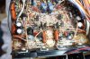
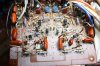
I have removed the input selector switch and cleaned it, all parts to be replaced have been removed from the F-2835 MM Head Amp board, and I have begun fitting the new components.
Picture to follow
Total removed parts count now: 131 - comprising
77 Electrolytic capacitors
8 Trimmers
9 Zener diodes
5 Resistors
32 Black Flags.
Picture to follow
Total removed parts count now: 131 - comprising
77 Electrolytic capacitors
8 Trimmers
9 Zener diodes
5 Resistors
32 Black Flags.