

You are using an out of date browser. It may not display this or other websites correctly.
You should upgrade or use an alternative browser.
You should upgrade or use an alternative browser.
Another AU-919
- Thread starter Hyperion
- Start date
-
- Tags
- au-919 reconditioning


Yes, leaving them - MV103's, (and also SV03's +2 x MV12), I know we have had this discussion before  - but will leave them for the time being, if I get 'issues' I'll get them out. Two previous AU-919's I have done have had no issues. I did it on the AU-X1 as it is allegedly quite a lot less stable than the AU-919, and could do with all the help it can get.
- but will leave them for the time being, if I get 'issues' I'll get them out. Two previous AU-919's I have done have had no issues. I did it on the AU-X1 as it is allegedly quite a lot less stable than the AU-919, and could do with all the help it can get.
Last edited:


F-2844 Small regulated PSU done except for finishing touches.
F-2845 - 15 components removed 12 capacitors and 3 glue damaged resistors, all glue cleaned. One of the legs on one of the resistors must have been half eaten through with glue corrosion, (it had green dots on it), I de-soldered it and the leg broke off very easily.
More later.
F-2845 - 15 components removed 12 capacitors and 3 glue damaged resistors, all glue cleaned. One of the legs on one of the resistors must have been half eaten through with glue corrosion, (it had green dots on it), I de-soldered it and the leg broke off very easily.
More later.
Driver assembly connected and tested - L&R bias set to 20mV and offset to sub 5mV levels.
All PSU voltages right on the money and dead clean. (I do need to re-check the ripple on the main supply rails).
Now I see the issue with the left channel when the Jump switch is off - DC offset jumping around - so the left channel of the Flat Amp has an issue - that'll be for tomorrow.
Time for a celebratory beer.
All PSU voltages right on the money and dead clean.
(I do need to re-check the ripple on the main supply rails).Now I see the issue with the left channel when the Jump switch is off - DC offset jumping around - so the left channel of the Flat Amp has an issue - that'll be for tomorrow.
Time for a celebratory beer.
Look what I have here - an AU-919 Flat Amp
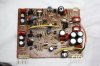
Before I removed it the fault was behaving like a dry joint, but now having closely examined it I can't find anything wrong physically. Note the Black Flag at the lower right, folded down and bent under the Dual FET, reason for this was probably clearance issues during assembly with the mating lever switch board.
There is little chance to fault find directly with 'power on' because access is so poor, so I am forced to change all the 'usual suspects' clean the board up, and see if that solves the problem, <sigh> if not at least it will have eliminated a few possible causes.
Removed parts 'body count' now 63 - part way through stripping Flat Amp.
Before I removed it the fault was behaving like a dry joint, but now having closely examined it I can't find anything wrong physically. Note the Black Flag at the lower right, folded down and bent under the Dual FET, reason for this was probably clearance issues during assembly with the mating lever switch board.
There is little chance to fault find directly with 'power on' because access is so poor, so I am forced to change all the 'usual suspects' clean the board up, and see if that solves the problem, <sigh> if not at least it will have eliminated a few possible causes.
Removed parts 'body count' now 63 - part way through stripping Flat Amp.
Last edited:

Considering the chances of getting another AU-919 to work on sometime, have you thought about making a set of extender cables so you could power it up outside the chassis?
This could quite easily be done as I am familiar with what is required. However, this is the first (of 3 I have seen) with a Flat Amp problem, which only affects one channel, could be something as simple as a noisy transistor, zener, or an 'open' Black Flag. So, unless this gets a lot more difficult to solve, I am pinning my hopes on an easy cure by changing the 'usual suspects'.
However, if the fault is still present afterwards, I'll do it the hard way.
Last edited:
Flat Amp complete

Black Flags gone, Glue is gone, Trimmers replaced, Zeners replaced, Electrolytic capacitors replaced. I have also performed a subtle swap of components from Right to Left channel, to speed fault finding should the Left channel problem remain.
NB: C15 & C16 aren't missing, they were never there
Total removed parts body count:
53 Electrolytic Capacitors
6 Trimmers
9 Zener Diodes
3 Resistors
20 Black Flags.
Black Flags gone, Glue is gone, Trimmers replaced, Zeners replaced, Electrolytic capacitors replaced. I have also performed a subtle swap of components from Right to Left channel, to speed fault finding should the Left channel problem remain.
NB: C15 & C16 aren't missing, they were never there
Total removed parts body count:
53 Electrolytic Capacitors
6 Trimmers
9 Zener Diodes
3 Resistors
20 Black Flags.
Last edited:

Multimode
Active Member
Excellent work!Flat Amp complete
View attachment 862741
Black Flags gone, Glue is gone, Trimmers replaced, Zeners replaced, Electrolytic capacitors replaced. I have also performed a subtle swap of components from Right to Left channel, to speed fault finding should the Left channel problem remain.
NB: C15 & C16 aren't missing, they were never there
Total removed parts body count:
53 Electrolytic Capacitors
6 Trimmers
9 Zener Diodes
3 Resistors
20 Black Flags.
I assume C21 and C22 positions have been bypassed as their neighbours have sufficient capacitance to cover the requirement?
Last edited:
I assume C21 and C22 positions have been bypassed as their neighbours have sufficient capacitance to cover the requirement?
Thank you.

Factory fit was 2 capacitors (for each channel) arranged in series to form a bipolar capacitor - these have been replaced with a single 'manufactured' audio quality bipolar - hence the shorting link across one component position in each channel.
Stop Press
Flat Amp left channel issue is a thing of the past - just tested perfectly - at a guess I would say one of the zener diodes was the culprit.
I'll obviously do some further checking as you said it was ok at first, and then developed the issue after a while. I did find a highly suspect joint on one of the capacitors at the output - but upon checking it was for the Right channel - so not the problem.
Last edited:

Pictures show yet another reason I like both restoring and collecting Sansui gear, so many of their designs used plug in boards making bench repair so much easier and accurate. If only the 8080/9090db units had plug in dolby boards instead of those nasty ribbon cables.
-Lee
-Lee