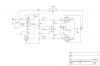
Hey Kegger, did you ever get a chance to look over this schematic (located in posts 189 and 190) ?? See any possible improvements? Thanks, Stan
"Quote:
Originally Posted by jaymanaa
Keg, what improvements can/would you make to that schematic?"
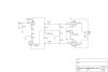
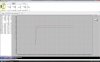
Well you guy's asked so I did load the schem up in spice and check it out.
With what I got from spice and some of my thoughts on getting just a touch more
current to that bottom part of the 12AX7 I'm posting what I would believe to be an
update, with this schem both sections now draw roughly the same current, there is a
touch less gain (so I modded the feedback circuit a touch as well) and in the originals
design the phase splitter was highly sensitive to the gain of the 12AX7, not just on the
section to section but on the gain it'self, meaning if you had the amp balanced well but
dropped in a different 12AX7 with a tad more or less gain than the one pulled from that
amp it would make a fairly large change in the phase balance, in this new version that is
greatly reduced so most any (well matched sections) 12AX7 should perform nicely.
You'll notice a pair of 27k resistors in parallel to provide the "balance" as there is no 13.5k
resistors easily found, as I believe Gordon suggests you could put a pot there, but I think
with gain/balance deal working better in this it may not really be all that needed/wanted.

(13k will actually work fine here)
I also changed the 47k input resistor to something less obtrusive, an the input impedance
to 330K just to use all the same resistors for builds/buy purposes, added grid stoppers to
the outputs an [screen resistors (may want to tailor those to taste, down to say 100ohm]
(grid stoppers aren't a necessity on these tubes)
To mod the feedback circuit "perfectly" someone really would need to put it on a scope,
also the 2 caps on that cathode of the top 12AX7 section can be removed if you can get
away with less gain in the amp an have a pre with gain you otherwise couldn't really turn
it to far previously, you may even want to tweak the feedback more by upping the resistor
from say the 4.7k I have there now to something like 10K? (scope it out to be sure)
Without having one of these in front of me I surely can't tweak it, and I don't have one, so
it is up to you guy's from here, but I believe these changes are quite solid.
Hope that is what you guy's had in mind an I was successful on improving the original design.
Edit: Also the supply to that front end should work well with 250-350v on it, 300v looks nice.
-----------
Edit: Recently did a rebuild of one of these and the 4.7K feedback resistor worked quite well.