You are using an out of date browser. It may not display this or other websites correctly.
You should upgrade or use an alternative browser.
You should upgrade or use an alternative browser.
Another Maggy Thread
- Thread starter jaymanaa
- Start date


jaymanaa
RIP 1961-2018
Nice work Jay. If you didn't notice, that rectumfier is a 5U4G in a 5U4GB bottle. A bit more drop than the GB - and people revere the G more than the GB as you probably already know
Ha, I didn't even notice. I just grabbed the first thing I found in a box of old rectum fires. I could use a little more juice, so I'll have to correct that.:yes:

jaymanaa
RIP 1961-2018
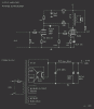
That's about 8 coats of Formby's tung oil, and yes, that metal inlay was a PITA. I originally planned to do a mahogany corner "inset", but screwed up the cut on the table saw. I didn't want to throw the base out, so I came up with that idea. It turned out OK, but getting it carved just right, took a lot of patience as well as exacto blades. The amp really looks cool in a dimly lit room. The copper reflects the filaments as does the finished cherry veneer. It sounds really nice too, so I think it will be around for a good long while.:yes: I'm trying to post the schematic, but I'm having trouble. I'll get it figured out though.:thmbsp:
The amp really looks cool in a dimly lit room. The copper reflects the filaments as does the finished cherry veneer. It sounds really nice too, so I think it will be around for a good long while.:yes: I'm trying to post the schematic, but I'm having trouble. I'll get it figured out though.:thmbsp: Un-educated question alert!!!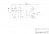
jaymanaa
RIP 1961-2018
why the extra 470k and b+ leg on pins 1 and 6 of 12ax7? Stan
Ha, because I goofed.

stanbp64
Well-Known Member
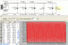
Keg or anyone, Is there a quick (simple) explanation for determining the load of the current tap (constant current) when modeling a p/s in psud2? How was the load determined in the attached example which came from an earlier post? Thanks, Stan ( i can't attach the schematic of the 8601 again)
Attachments

Kegger
R.I.P. 1/12/1966 - 6/1/2017
Keg or anyone, Is there a quick (simple) explanation for determining the load of the current tap (constant current) when modeling a p/s in psud2? How was the load determined in the attached example which came from an earlier post? Thanks, Stan ( i can't attach the schematic of the 8601 again)
Pretty easy and straight forward.
How much current is in each output tube?
So for this let's say 35ma, times that by 2 get 70ma, toss a couple for losses, 72.
Each tube in the front end draws lets say 1ma each and each screen say 3.5ma
so we have 2 plus 7 for a stereo amp, toss in 1 for loss we get 10.
Measure the current in each tube by deviding the voltage present at the cathode
by it's cathode resistor value, calculate your total current an plug it into the sim.
The screen is a little more difficult to measure, usually look at the tube data sheet
for that, but it is very small anyway so not much to make a significant difference.
Kegger
R.I.P. 1/12/1966 - 6/1/2017
You mean your Push Pull one?
If so I haven't really looked it over that hard, many things goin on in my head.
(when I get a chance I can see if I have any suggestions though)
If it's the single ended one I did up I'm done with it, works great! (Listening to it)
If so I haven't really looked it over that hard, many things goin on in my head.
(when I get a chance I can see if I have any suggestions though)
If it's the single ended one I did up I'm done with it, works great! (Listening to it)
jaymanaa
RIP 1961-2018
You mean your Push Pull one?
If so I haven't really looked it over that hard, many things goin on in my head.
(when I get a chance I can see if I have any suggestions though)
If it's the single ended one I did up I'm done with it, works great! (Listening to it)
The PP one back just a few posts. Take your time.:yes:
stanbp64
Well-Known Member
Pretty easy and straight forward.
How much current is in each output tube?
So for this let's say 35ma, times that by 2 get 70ma, toss a couple for losses, 72.
Each tube in the front end draws lets say 1ma each and each screen say 3.5ma
so we have 2 plus 7 for a stereo amp, toss in 1 for loss we get 10.
Measure the current in each tube by deviding the voltage present at the cathode
by it's cathode resistor value, calculate your total current an plug it into the sim.
The screen is a little more difficult to measure, usually look at the tube data sheet
for that, but it is very small anyway so not much to make a significant difference.
Please excuse my ignorance but I am trying to get a handle on this. It seems easy enough if I have an amp to measure but what if all I have is a schematic? Take the attached RH84 schematic for example. how do I figure the current to use as current tap if modeling the p/s?