• The move to the new server is done. There are some software and database maintenance updates in process. This has us passing the hat around to help out. We appreciate any donations. Seriously, even a dollar helps. The payment page may be found here - https://www.audiokarma.org/support.html

Another Maggy Thread

Well, you just add it up.:thmbsp: If you're talking about the load for PSII, just figure it out. You have an EL84, so you need to estimate the cathode current, and the grid current (look up the maximum values and figure 80%). Then figure a couple mA for each small signal tube. Add it all up and there's your load for PSII. It doesn't look at heaters.:no:
 
First you need to make sure you have TDSL.. (EVERY TUBE PERSON NEEDS TDSL)
http://www.duncanamps.com/tdslpe/download.html

(the following is ONE way of doing it fairly close)

Then you bring up the EL84, go to (short data)

look down to the 6th row, you'll see EL84 running pentode with a voltage of 300,
you'll see it has a shared cathode resistor of 130ohms, double that same value for
a single tube to get the same current, so 260ohms, pretty close to the schematic
of 270 ohms, now look at the current 72-92, so figure the middle at 82, that is for
2 tubes which a single ended stereo amp will have, now look at the screens current,
8-22 so call it 15. now you have 82 + 15 for 97 on the output section.

Now bring up the 12AT7, go to (Data sheet links)

Go down to the 3rd row, click it to bring up the data sheet, at the top of the second
page you'll see (plate supply voltage) of 250v with a current of 10ma when using that
200ohm resistor, now here your running 250 ohm but a little higher supply, but I would
guestimate 8ma for each tube for 16 total. (Probably less with the RC to the front end)

(for sake of discussion)
So now you have 97 + 16 = 113 add a couple extra call it 115 for the entire amp.

He says MINIMUM 20H choke at a 50ma, were running over 100ma here but still that
choke is going to have a decent resistance like say 300ohm.

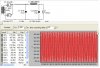
So the attached pic is what I would presume the designer was intending on that supply.

-----------

WHEW, please don't have me do that again............ :)
 

Attachments

  • RH84_supply.JPG
    RH84_supply.JPG
    73.5 KB · Views: 51
Good job, Kegger! ;)

I decided to try the screen taps on the James 6123HS OPT's, with my RH84 breadboard circuit.

I didn't really like it compared to just using B+ for the screens. Can't really say, it seemed thinner sounding I suppose.
Who knows...... But I do know the designer made a nice sounding SEP EL84 circuit.
 
Ok, I promise I won't do it again.:nono: I guess what I was wondering if it could be calculated (without any estimating) from the info on the schematic(plate volt., cath. res., etc) Guess I was making it harder than it needed to be. Once again, I appreciate your help! :D Stan
 
Ok, I promise I won't do it again.:nono: I guess what I was wondering if it could be calculated (without any estimating) from the info on the schematic(plate volt., cath. res., etc) Guess I was making it harder than it needed to be. Once again, I appreciate your help! :D Stan

Unfortunatly there is not enough info.

All he gives is the power supply voltage, there are no voltages on the schematic at all.

If just the cathode voltages were present then everything could of been calculated easily.

-----------

But what I did is what you would do when building from scratch and having no schematic to
go by, if you follow just what I did you could build an entire amp an have it work as predicted. :D
 
Good job, Kegger! ;)

I decided to try the screen taps on the James 6123HS OPT's, with my RH84 breadboard circuit.

I didn't really like it compared to just using B+ for the screens. Can't really say, it seemed thinner sounding I suppose.
Who knows...... But I do know the designer made a nice sounding SEP EL84 circuit.

Mike if you were goin UL on that amp:

I suggest either removing the 100K RFB resistor or at least tripling it's size.

In pentode all that feedback is needed, but in UL or Triode it won't be an the
amp MAY sound a whole lot better without or at least reduced substantiually.

Then you'll want to adjust your cathode resistor accordingly, as in pentode an
UL or Triode the tube will draw different current, so to truly compare you want
to run both with the same current. :)

-------------------------------------------------

Not suggesting that UL or Triode "will" be better sounding then the RH84 setup
but the RH84 is optimized from the designers point of view, the same would be
needed in UL or Triode to do a fair comparison.

(I'm sure I'm not really telling you anything you don't know, but for others that
may possibly get a wrong view)
 
That's cool!!! I have copied and pasted your advise to my h/d so I'll always have it. I was trying to calculate the voltage on the cathode( using B+, drop in opt, drop thru el84 etc, and it wasn't working out for me. Anyway, it's obvious from your advice/example that making a few educated assumptions puts you close enough! Thanks again!:yes:
 
Bravo!

First you need to make sure you have TDSL.. (EVERY TUBE PERSON NEEDS TDSL)
http://www.duncanamps.com/tdslpe/download.html

(the following is ONE way of doing it fairly close)

Then you bring up the EL84, go to (short data)

look down to the 6th row, you'll see EL84 running pentode with a voltage of 300,
you'll see it has a shared cathode resistor of 130ohms, double that same value for
a single tube to get the same current, so 260ohms, pretty close to the schematic
of 270 ohms, now look at the current 72-92, so figure the middle at 82, that is for
2 tubes which a single ended stereo amp will have, now look at the screens current,
8-22 so call it 15. now you have 82 + 15 for 97 on the output section.

Now bring up the 12AT7, go to (Data sheet links)

Go down to the 3rd row, click it to bring up the data sheet, at the top of the second
page you'll see (plate supply voltage) of 250v with a current of 10ma when using that
200ohm resistor, now here your running 250 ohm but a little higher supply, but I would
guestimate 8ma for each tube for 16 total. (Probably less with the RC to the front end)

(for sake of discussion)
So now you have 97 + 16 = 113 add a couple extra call it 115 for the entire amp.

He says MINIMUM 20H choke at a 50ma, were running over 100ma here but still that
choke is going to have a decent resistance like say 300ohm.

So the attached pic is what I would presume the designer was intending on that supply.

-----------

WHEW, please don't have me do that again............ :)

Bravo!

Thanks much for the synopsis.

Dan
 
Any more Maggies news?

Jay is yours still the same?

Stan?

Anybody?

(Yes I'm trying to keep the thread alive Jay) :)
 
Any more Maggies news?

Jay is yours still the same?

Stan?

Anybody?

(Yes I'm trying to keep the thread alive Jay) :)

actually yes :D

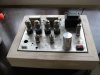
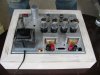
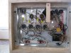
I just finished my first ever (SUCCESSFUL) magnavox power suppy rebuild :banana: I've done a few minor recaps, and 'mods' but this is truly the first one I got 100 % right.

it's a 88- series 6V6 P/P amp headed to botrytis . . .

I used a 4 element elec. cap from Angela Electronics, and I gotta say the BIGGEST difference in power transformer heat is using a separate electrolytic cap for the cathode - factory one was 'in the can' and the PT was ALWAYS super hot . . . now even after 10 hours on, it stays nice and warm . . . :thmbsp:

I still need to veneer the base . . hopefully this weekend :thmbsp:

attachment.php


attachment.php


attachment.php
 

Attachments

  • IMG_8781.JPG
    IMG_8781.JPG
    71.4 KB · Views: 268
  • IMG_8783.JPG
    IMG_8783.JPG
    82.4 KB · Views: 266
  • IMG_8784.JPG
    IMG_8784.JPG
    91.2 KB · Views: 266
another trick, which I stole from Gordon (heh heh) is to wire the extra 6.3 V heater wire in reverse to the incoming AC line -drops the voltage for me from 126 (at the wall) to about 117 V goijng into the PT after the fuse & switch.

I owe most of my success to GordonW, mhardy, and the rest of the AK brain trust - thanks guys !
 
Nice Markus, Very nice!

-----------

Were you possibly thinking of rewiring the heaters so you can use 12AX7 instead 6EU7?
 
That looks great Markus. I have just started collecting parts for a scratch build of the modded maggie Jay has posted. I have the trannies from a 930x, can't decide whether to use those output trans. or something with 8 ohm secs.
Stan
 
Keg, what improvements can/would you make to that schematic?

Hey Kegger, did you ever get a chance to look over this schematic (located in posts 189 and 190) ?? See any possible improvements?

Jay, have you used the amp anymore? Any different impressions?
Thanks, Stan
 
Hey Kegger, did you ever get a chance to look over this schematic (located in posts 189 and 190) ?? See any possible improvements?

Jay, have you used the amp anymore? Any different impressions?
Thanks, Stan

I ran it for about a week or two, then put it away (that's what happens to most of my builds). You're talking about the one I did with 6GK6s right?
 
As for sound, it is an exceptional performer. It may be all in my head, but I think the 6GK6 is a little better down low than the 6BQ5. It just sounds more controlled in the lower frequencies.:yes: I'm very curious as to how a Dolly Clone would sound with 6GK6s subbed in.:scratch2:
 
Back
Top Bottom