• Please note that Audiokarma will be offline briefly for updates early on Monday morning, September 28th.

Another Maggy Thread

Just FYI on the rectifiers for those messing with these Maggie amps. (or others)

The 5Y3 and 5U4 are both directly heated NON slow warmup rectifiers.
They both have a fairly large voltage drop, meaning the voltage will sag more.

The 5Y3 is a 2a heater, 125ma max
The 5U4 is a 3a heater, 225-275ma max (depending which version)

There are 2 other rectifiers I would use in there place, (drop in, same pinout)

The 5AR4 is a 2a heater, 225ma max
The 5V4 is a 2a heater, 175ma max

The 5V4 and 5AR4 are both indirectly heated, slow warmup rectifiers.
They both have a farly low voltage drop, meaning the voltage won't sag as much.

They can both handle fairly large cap inputs, (Won't need as much without the sag)

5V4's, plentiful an rather inexpensive, plus they come in the 5V4G variety, ST shape!

Dang it Keg, I was just getting ready to list a bunch of 5U4s on epray.:D
 
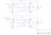
One suggestion for those using Maggie 175 or 88xx series circuits, whether in an original amp or built from scratch- I have found that if you use a POT as the voltage divider for the paraphase phase splitter, rather than fixed resistors, you can DIAL IN the ABSOLUTE CORRECT balance between the positive and negative phases of the signal. IME, this greatly reduces distortion- at factory values, with the tubes I had in my amp here, the measured harmonic distortion at 1KHz was around .7%; after dialing it in, I was able to reduce that to .14%! This may vary, depending on the balance of the 12AX7 tube, the balance of the output tubes and transformers and such- the nice thing, is that with this adjustment, you can dial it in, NO MATTER WHAT tubes or other components are in the circuit!

Of course, you will need an oscilloscope or access to a distortion analyzer to do this right... but, if you have access to such, it really DOES make a difference!

I've taken the liberty of modifying the schematic posted earlier in this thread; the circuit elements inside the red boxes are where the changes have taken place:

attachment.php


Regards,
Gordon.
 

Attachments

  • magnavox 175 with phase splitter adjust.PNG
    magnavox 175 with phase splitter adjust.PNG
    68.8 KB · Views: 805
Excellent schematic Update

Thanks gordon!

good thing I have a couple of scopes hiding under my bed. . .

courtesy of my past life as a computer service tech: been a long time since you needed a scope on tape drives, plotters and stuff.

Dan
 
Yep, then you can take the pot out, measure it and put in a resistor. Kind of like "tuning" a pentode driver. Would the value change with different tubes (need to re-adjust)?
 
Yep, then you can take the pot out, measure it and put in a resistor. Kind of like "tuning" a pentode driver. Would the value change with different tubes (need to re-adjust)?

YES... it would change due to gain differences or transconductance differences in any of the tubes (input or output), and differences in balance between the 12AX7 halves, of the input tubes. As well as any cathode or anode resistor drifts over time, anywhere in the front end.

So, I made the decision to make it permanent in the last amp I built. So it can be re-calibrated at re-tube time...
 
YES... it would change due to gain differences or transconductance differences in any of the tubes (input or output), and differences in balance between the 12AX7 halves, of the input tubes. As well as any cathode or anode resistor drifts over time, anywhere in the front end.

So, I made the decision to make it permanent in the last amp I built. So it can be re-calibrated at re-tube time...

I figured that, I was just thinking of "knob turners" if you sold it (I guess you could mount it underneath and use a screwdriver slot type pot) I think I'll try it out on my next Maggie (this one).:D
 
I got to fiddle with this thing again, due to waiting on parts for other stuff. Nothings polished or even final sanded yet, but the pic will give an idea where it's headed. I plan to laminate the chassis deck with Cherry veneer (if they have it at the lumber yard). The little copper box thing will get polished and cleared, and have a black mesh "screen" around the sides and back. The copper should shine up pretty good, so I'll have to be careful putting in the power tubes sockets, so the lion share of the heat won't reflect back to the tube. If you look close you can see a little brass inset in the corner by the Maggie badge, That was pretty dang hard to do, but when polished it matches the badge nicely. Not sure on the other corner yet.:scratch2:
 
Last edited:
Reading this post I put away the VM 165 im converting to guitar amp duty and opened Fibber McGee's closet.

My tecnique for finding what I know is there somewhere under that pile is to mess around the pile dangerously until it falls on you. Then as you are putting all back ascew....whaa..La. THERE IT IS!!

So I dug out a Magnavox 9302-00 chassis.
Looks alot like yours there but a little different. Any thoughts on this chassis?
I saved the Magnavox emblem and taped it to the chassis when I disasssembled the console this came from.

Should we keep a Magnavox thread in view at all times?

All I need now is a schemo and a couple hours
Thanks for the inspirational boost.
 
Cool, I think I may have that schematic here somewhere (I'll look). I've been working on the TX cage for this all morning, but have made decent progress. I soldered a small strip of thin brass angle to the edge that will rest on the cherry, and some #4 flat head screws to the back, which will hold the black screen. The thing about these console amps is, they sound as good as you can make them look.:music:
 
Last edited:
You are going all out with that trans box. It will definately be one of a kind.
I dont think I'll go that far.
In my planning thought bubble is
- an on/off switch
- adding input and out put circuit protection
- some kind of wood edging as you've done
- putting the powercord and speakers connectors out the back panel
- some rubber feet

Ive made little cases for the project amp and its tuner before but havent made an aesthetically pleasing stand alone chassis as of yet.

Its been in my head to edge my Motorola with wood and that one may be next.

We've got a Great Hardwoods store here and considering the small amount needed, I could probably get a piece of extremely nice wood enough to do three or four of these for $20-$40

 
Here's the final layout, now for a few more coats of tung, and some polishing.:yes:
 
Last edited:
Oh, now you've gone commercial.
That looks fantastic.

Did I miss something?
Is that contact paper over the top of the chassis?

Thats marketable for sure
 
Back
Top Bottom