• The move to the new server is done. There are some software and database maintenance updates in process. This has us passing the hat around to help out. We appreciate any donations. Seriously, even a dollar helps. The payment page may be found here - https://www.audiokarma.org/support.html

Another Maggy Thread

Yeh--more schemos

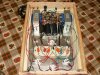
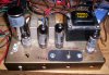
Thanks Jay and Knifefighter. I just wasn't sure about the values of the components if these mods were made to the el84 amp. Knife-- another schematic would be great. I love the Maggie designs--- I have built 3 of them with good results (all se el84). Here is the latest, a 86-xx w/o the eq cicuitry.
 

Attachments

  • P1000892.jpg
    P1000892.jpg
    80.5 KB · Views: 158
  • P1000843.jpg
    P1000843.jpg
    155.7 KB · Views: 167
Thanks Jay and Knifefighter. I just wasn't sure about the values of the components if these mods were made to the el84 amp. Knife-- another schematic would be great. I love the Maggie designs--- I have built 3 of them with good results (all se el84). Here is the latest, a 86-xx w/o the eq cicuitry.

beautiful work on that 86- chassis :yes:

I have a crusty one of those that needs to be redone - does magnavox friends site have a schematic to show what EQ guts to get rid of ?
 
Thanks Jay and Knifefighter. I just wasn't sure about the values of the components if these mods were made to the el84 amp. Knife-- another schematic would be great. I love the Maggie designs--- I have built 3 of them with good results (all se el84). Here is the latest, a 86-xx w/o the eq cicuitry.

Nice work, that's a beautiful amp.:thmbsp:
 
86xx

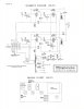
Thanks. While I am getting better at building tube amps I am still far from really understanding all about how they work. I have learned alot lurking about this forum. Anyway, I think the amp sounds really good with my diy voight pipes w/ 8" Audio Nirvana drivers. Here is the schematic from the Yahoo site that I used. I hope they don't mind me sharing it. Stan
 

Attachments

  • 8601_MagAmp_Without_EQ.jpg
    8601_MagAmp_Without_EQ.jpg
    57.9 KB · Views: 451
86xx

Here is re-drawn schematic. I also added 390 ohm resistors to pins 9 and 4 to ground for balance pot on preamp. Not real sure I needed to.
 
Another update.

(THIS IS BASICALLY JUST A CLEANUP AND STREAMLINE TO THIS AMP)
There are better circuits I would more then likely use instead of the maggie.

Just got done doing the same Maggie 86-01 EL84 amp, Some suggestions!
(it's still using the original basic circuitry here)

The original outputs don't have UL taps, and if yu use some that do the bias
will be off, quite HIGH actually, also I suggest removing the input cap an get
rid of the rediculousy high 6.8 MEG OHM input resistor to something like 270K.
(If going UL or Triode I suggest a 150OHM shared cathode resistor)

I added the 33K and 6.8K feedback resistors to stay at 39K of loop, going to
6.8k is just a bit to much feedback for me here. (ended up at 20k in the end)
(10k feedback resistor is as low as I would go)

I tweaked the front end to better run the 6EU7, with a bit more voltage and
current so it is not quite as starved as it is in it's original form.

I see on the other circuit posted there is no voltage to the top section driver,
and the feedback should not be connected to both the grid of the driver and
the cathode, just the cathode. :D

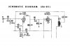
I'm posting my updates as schem and the original driver portion, you can see
the caps in the driver cathode section, those are the ones removed to make
the amp run full range and get rid of the EQ.

Since there is no room for choke on the original chassis I beefed up the power
supply with good amount more of capacitance to make the amp a bit cleaner,
should help with the amp now being full range as well.

I upped the cathode bypass cap value to 220uf (it was what I had on hand)
I would have gone with 300-450uf if I had the cap, that should be fine.

I will do the other amp later, removing loop and going to a 12AT7 type driver.

(EDIT) I forgot, I'd added individual 10ohm cathode resistors to each output
before the shared 100ohm so you can measure current in each tube separate.
(shematic updated, I may update later if/when I find more tweaks) :)

This rebuild was just that, a rebuild, not a full makeover with new circuitry, it
was done to have "stock" setup perform as best it could for what it is and to
evaluate the original circuitry against a totally redesigned version I plan later.

Only large changes are the beefed up power supply, the circuitry is the same
stock circuitry just that EQ stuff is omitted and values "tweaked" a bit there.
 

Attachments

  • MAGGIE_8602_INP_jpg.jpg
    MAGGIE_8602_INP_jpg.jpg
    42.5 KB · Views: 143
  • maggie8601_km_ed1_m3.JPG
    maggie8601_km_ed1_m3.JPG
    55.7 KB · Views: 121
(THIS IS BASICALLY JUST A CLEANUP AND STREAMLINE TO THIS AMP)
There are better circuits I would more then likely use instead of the maggie.

Just got done doing the same Maggie 86-01 EL84 amp, Some suggestions!
(it's still using the original basic circuitry here)

The original outputs don't have UL taps, and if yu use some that do the bias
will be off, quite HIGH actually, also I suggest removing the input cap an get
rid of the rediculousy high 6.8 MEG OHM input resistor to something like 270K.
(If going UL or Triode I suggest a 150OHM shared cathode resistor)

I added the 33K and 6.8K feedback resistors to stay at 39K of loop, going to
6.8k is just a bit to much feedback for me here. (ended up at 20k in the end)
(10k feedback resistor is as low as I would go)

I tweaked the front end to better run the 6EU7, with a bit more voltage and
current so it is not quite as starved as it is in it's original form.

I see on the other circuit posted there is no voltage to the top section driver,
and the feedback should not be connected to both the grid of the driver and
the cathode, just the cathode.

I'm posting my updates as schem and the original driver portion, you can see
the caps in the driver cathode section, those are the ones removed to make
the amp run full range and get rid of the EQ.

Since there is no room for choke on the original chassis I beefed up the power
supply with good amount more of capacitance to make the amp a bit cleaner,
should help with the amp now being full range as well.

I upped the cathode bypass cap value to 220uf (it was what I had on hand)
I would have gone with 300-450uf if I had the cap, that should be fine.

I will do the other amp later, removing loop and going to a 12AT7 type driver.

(EDIT) I forgot, I'd added individual 10ohm cathode resistors to each output
before the shared 100ohm so you can measure current in each tube separate.
(shematic updated, I may update later if/when I find more tweaks)

This rebuild was just that, a rebuild, not a full makeover with new circuitry, it
was done to have "stock" setup perform as best it could for what it is and to
evaluate the original circuitry against a totally redesigned version I plan later.

Only large changes are the beefed up power supply, the circuitry is the same
stock circuitry just that EQ stuff is omitted and values "tweaked" a bit there.

damn . . you go Kegger :ntwrthy:

this is whats great about audiokarma - I can just follow tube and speaker recipes, and the **** just works - sounds great, and stomps all over systems 10X as expensive. Not to mention you have a huge network of AK Brothers (for lack of a better term) there for you when you need them . .

too cool :smoke:

I think my hot rodded 93 chassis might have to come under the knife soon for a 12a** conversion :scratch2:
 
I'm tryin Markus, I'm tryin! (Goin slow here lately, to much goin on)
(just did this one to find out how they perform)

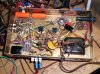
Here's a couple pic's, (No I have not cleaned it)

I added a fuse holder on the side and an on/off switch on top.

Had it at the last SMAC meet on some big JBL/s, it did allright. :smoke:
 

Attachments

  • btm_832.JPG
    btm_832.JPG
    126.5 KB · Views: 138
  • top_844.JPG
    top_844.JPG
    100.6 KB · Views: 289
What's the purpose of the 180K resistor? (150K on the original schematic.)

The resistor before the 6EU7 470K/330K load R, and connected to the cathode of 6EU7.
 
Mike I'm not sure of it's "original" purpose, but in this application with limited B+
and a 12AX7 it helps quite a bit in getting good plate and cathode voltage/bias
an gain than under more traditional settings would be possible.

Without it you end up with 67v on the plate .3v cathode an .35ma, then with it
you get 115v on the plate, 1.2v cathode and .45ma through the 6EU7/12AX7, I
simmed the circuit, tweaking the values to get the best I could with this voltage.
If you tried without it, you either sacrifice voltage/current/gain so much more.

If you remove it, and up your cathode resistor to 3.3k so you end up with same
plate/cathode voltage and same current you get 1/4th the gain. If you were to
run a bypass cap on the drivers cathode you end up with the same gain on both,
but it's through the roof an would require tons of feedback to knock it back down.

I had never seen it before, an was a little befuddled with it being there, I did try
doing away with it, but the circuit runs soo much better with it in there, so I set
out to tweak it as best I could for values that I feel help the 6EU7 settings.

With plate loads needed for a 12AX7/6EU7, and this low voltage of roughly 225v
leaves little to work with, I'd prefer to have 350v - 500v to use a nice plate load
and still get usable voltage in the circuit, hence why I like to run lower mu/plate
resistance tubes so I can run lower loads and get good usable voltages, but on
this one I wanted to stick to the original schem as much as possible. I have the
identical amp I'm going to do a complete redesign on using a different driver and
will not be using loop or that voltage resistor, I'll be using plate to plate/grid from
the output tubes plate back to the drivers, it will give me the feedback and more
voltage available to the driver, not to mention the lower plate load on the drivers
will give me more voltage available at the same time.

Sorry for rambling, most probably already know or don't care what I'm saying. :)
 
Adding an internal powerline voltage reduction using the unused extra 6.3V winding

An aside: I have a copy of this amp, and I used the extra unused 6.3V power transformer secondary winding (W and V) as a powerline voltage reducer. I found a mating connector for J2, which made this easy to do: But other wiring methods will serve. Connect J2 pin 1 to pin 3, and separately connect pin 7 to pin 10. Now to be sure that we got the phasing right: put your voltmeter (set to expect 120VAC) between pin 5 and pin 1 (which is across the original primary). You should see the powerline voltage minus 6.3VAC. If it reads the powerline plus 6.3VAC, you'll need to swap the W and V leads. That would then be pin 1 to 7, and separately pin 10 to 3. That should get you the reduced voltage. Check the secondary voltages to be sure that they did in fact go down approx 5%.

attachment.php


You could add a power switch in between one of the above connections.

This will have the amp "think" that it's running off old fashioned powerline voltages, and not today's inflated powerline voltages.
 
An aside: I have a copy of this amp, and I used the extra unused 6.3V power transformer secondary winding (W and V) as a powerline voltage reducer. I found a mating connector for J2, which made this easy to do: But other wiring methods will serve. Connect J2 pin 1 to pin 3, and separately connect pin 7 to pin 10. Now to be sure that we got the phasing right: put your voltmeter (set to expect 120VAC) between pin 5 and pin 1 (which is across the original primary). You should see the powerline voltage minus 6.3VAC. If it reads the powerline plus 6.3VAC, you'll need to swap the W and V leads. That would then be pin 1 to 7, and separately pin 10 to 3. That should get you the reduced voltage. Check the secondary voltages to be sure that they did in fact go down approx 5%.

attachment.php


You could add a power switch in between one of the above connections.

This will have the amp "think" that it's running off old fashioned powerline voltages, and not today's inflated powerline voltages.

I really want to do this to my 88- series 6V6 P/P amp . . . thanks for explaining it so well :thmbsp:
 
I see on the other circuit posted there is no voltage to the top section driver,
and the feedback should not be connected to both the grid of the driver and
the cathode, just the cathode. :D

Thanks Kegger, I removed that schematic from the post. I didn't proof read it well enough before posting. Fortunately I did not build my amp by the schematic, rather I drew it up after amp was complete. Now i have to implement your mods.
As a side question, What is the current req.'ment for the power tranny? The transformer on my diy amp gets quite hot after about an hour of use. It is a hammond 260-0-260 90ma tranny. heater winding is 3.5 i believe.( not at home right now so i can't look.)
 
In Ultraliner or Triode with that cathode resistor your probably running 50ma per EL84
and 2ma per each drivers section, so 104ma give or take total, yah taxing that tranny
a bit there, it will probably live but yes get hot. (up the cathode resistor drop current)

EL84 .76a heater each, an 6EU7 is .3a an EZ81 is 1a, so we get 1.52 + .3 + 1 = 2.82a.

Check your voltage at the plate of the EL84, and check the cathode, lets see what you
are actually running the EL84's at.
 
I really want to do this to my 88- series 6V6 P/P amp . . . thanks for explaining it so well :thmbsp:

Thanks, but be sure that the unused heater winding is in fact isolated, and there's no centertap or such connected to ground or something else inside the amp. Then you should be good to go.
 
86xx

In Ultraliner or Triode with that cathode resistor your probably running 50ma per EL84
and 2ma per each drivers section, so 104ma give or take total, yah taxing that tranny
a bit there, it will probably live but yes get hot. (up the cathode resistor drop current)

EL84 .76a heater each, an 6EU7 is .3a an EZ81 is 1a, so we get 1.52 + .3 + 1 = 2.82a.

Check your voltage at the plate of the EL84, and check the cathode, lets see what you
are actually running the EL84's at.

Kegger, thanks for your help. Measured voltages and i get 300vdc on the plate and about 9vdc on the cathode running in triode mode. (under load) Shouldn't the plate be at about 250? I think I am going to redo this amp to your schematic w/ option of ultralinear or triode mode. I would like to stick with this power tranny so any additional tips for easing the burden on it will be appreciated. What would you suggest for the cathode resistor value? Thanks, Stan
 
Your high voltage is to be expected, Hammond tranny is a little higher then stock.
(So is the stock running on todays voltage, unless knocked down like Wa2ise shows)

Here is what I would do, change your 100 ohm resistor in the power supply to 200.
Change your common cathode resistor on the EL84's to 125ohm, up the bypass cap
to 300-450uf, then I would run 10ohm resistors from the EL84 cathodes (1 each) to
the 125ohm/bypass cap junction (simular to my schem) so you can measure each of
the EL84's currents seperate to match the tubes.

Don't worry about the high voltage, your plenty safe, and a little extra will help a bit.
 
86xx

Ok, Thanks Kegger.. I think I'm gonna tear this baby apart and rebuild it per your schematic and suggestions. I even have the original 86xx transformer--I used it in a little guitar amp---that I may swap into the rebuild. That will give me a couple of mini-projects to keep me from spending money on another big project. (Although I do want to build the 93xx or the 6v6 amp sometime) Gotta luv Tubes! One more question for you or anyone, If I wanted a cathode resistor for each El84 would i use the same values for res. and bypass cap you suggested for both ( I am uncertain how to determine the cathode resistor) and also would the el84 cathodes still be tied together as they are with a shared cathode resistor? Oops, that was 2 questions. Thanks again, Stan
 
What do you use to sim it up Kegs?

I
simmed the circuit, tweaking the values to get the best I could with this voltage.

Hey Kegger,

Way cool info.

What do you use to sim this stuff up?

I need something to help me out with my mad scientist experiments.

Scully keeps telling me stuff about biology when I try to build circuits and none of it applies. She won't listen to me tell her it is a silicon based life form at all!

Knife - making a list to replace parts pilfered from my maggie stockpile
 

Attachments

  • Scully helps with inventory small (2).JPG
    Scully helps with inventory small (2).JPG
    147.3 KB · Views: 59
  • Scully helps with inventory small (4).JPG
    Scully helps with inventory small (4).JPG
    183.9 KB · Views: 65
Ok, Thanks Kegger.. I think I'm gonna tear this baby apart and rebuild it per your schematic and suggestions. I even have the original 86xx transformer--I used it in a little guitar amp---that I may swap into the rebuild. That will give me a couple of mini-projects to keep me from spending money on another big project. (Although I do want to build the 93xx or the 6v6 amp sometime) Gotta luv Tubes! One more question for you or anyone, If I wanted a cathode resistor for each El84 would i use the same values for res. and bypass cap you suggested for both ( I am uncertain how to determine the cathode resistor) and also would the el84 cathodes still be tied together as they are with a shared cathode resistor? Oops, that was 2 questions. Thanks again, Stan

When you split the cathode resistors you Double the value.

So it would be between 250-270ohm on each one, with it's own bypass cap.
(Yes they would be comepletly seperate from each other)

----------

The Sim program I use is Multisim, they use to have a free trial download, it is
probably to expensive for just a diy'er to do tube stuff if you purchase the full
version of the program.
 
Back
Top Bottom