• The move to the new server is done. There are some software and database maintenance updates in process. This has us passing the hat around to help out. We appreciate any donations. Seriously, even a dollar helps. The payment page may be found here - https://www.audiokarma.org/support.html

Another Maggy Thread

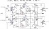
Made what I believe to be the last change in this amplifier. :)

Added another 4.7K resistor in paralell to the other 4.7K in the power supply.
This upped the screen and front end voltage to 255v, it provides a bit more
headroom in both the front end and output section. (changed fbk to 20k)

The amp can play a bit louder before clipping, and overall sounds punchier. :guitar:

An added bonus is you can really tell a difference in driver tubes, the sylvania
sounds like a sylvania, clean crisp, hifi sounding, a mullard well sounds like the
mullard is suppose to, very bluesy with more emphasys on bass/mids.

The amp I would now consider quite a nice little performer! :thmbsp:
(updated the schematic)
 
Now all we need

Now all we need to do is mod that schematic for 12Ax7 or 12AT7.

Or maybe we already have one that is so so close floating around.

Got to check and see if multisim arrived today and hope I am capable of using it :)

I was glad to see you were able to pull those voltages up like you wanted Kegger.


Dan
 
Mike I'm not sure of it's "original" purpose, but in this application with limited B+
and a 12AX7 it helps quite a bit in getting good plate and cathode voltage/bias
an gain than under more traditional settings would be possable.

Without it you end up with 67v on the plate .3v cathode an .35ma, then with it
you get 115v on the plate, 1.2v cathode and .45ma through the 6EU7/12AX7, I
simmed the circuit, tweaking the values to get the best I could with this voltage.
If you tried without it, you either sacrifice voltage/current/gain so much more.

If you remove it, and up your cathode resistor to 3.3k so you end up with same
plate/cathode voltage and same current you get 1/4th the gain. If you were to
run a bypass cap on the drivers cathode you end up with the same gain on both,
but it's through the roof an would require tons of feedback to knock it back down.

I had never seen it before, and was a little befuttled with it being there, I did try
doing away with it, but the circuit runs soo much better with it in there, so I set
out to tweak it as best I could for values that I feel help the 6EU7 settings.

With plate loads needed for a 12AX7/6EU7, and this low voltage of roughly 225v
leaves little to work with, I'd perfer to have 350v - 500v to use a nice plate load
and still get usuable voltage in the circuit, hence why I like to run lower mu/plate
resistance tubes so I can run lower loads and get good useable voltages, but on
this one I wanted to stick to the original schem as much as possable. I have the
identical amp I'm going to do a complete redesign on using a different driver and
will not be using loop or that voltage resistor, I'll be using plate to plate/grid from
the output tubes plate back to the drivers, it will give me the feedback and more
voltage available to the driver, not to mention the lower plate load on the drivers
will give me more voltage available at the same time.

Sorry for rambling, most probably already know or don't care what I'm saying. :)


Hell, I care.....you threw out some pretty good points/ideas there. You almost got me wanting to rip apart
one of my Magnavox amplifiers after that reply, and try some of those things.

I should lash up the breadboard and try that circuit sans power supply. I could try the RH84 circuit as well,
since I have some 12AT7's around here.

Once I get the Altec amp going......
 
Yeh Keg, maybe use that extra 6v winding to increase the B+, but it probably wouldn't get you much. Maybe use the 5v winding too, and go SS rectification. That might get you some "workable" voltage.:scratch2:
 
I'm done with this particular amp. (I like EZ81's to) :)
It performs well and the funky voltage technique works.

You can use a 6EU7 or a 12AX7 in this with no problem, just wire the pins for either.
The second one will get a different circuit, along the lines of the RH84 one mentioned.
 
Cool, I think I may have that schematic here somewhere (I'll look). I've been working on the TX cage for this all morning, but have made decent progress. I soldered a small strip of thin brass angle to the edge that will rest on the cherry, and some #4 flat head screws to the back, which will hold the black screen. The thing about these console amps is, they sound as good as you can make them look.:music:

Hey, do you have that 9302 schemo? That'd be great. I've gone as far as I can without a schematic. Everything is set as it is going to be visually, now I need to replace a resistor or two I think before I variac it up. At least one is burnt and unreadable. Probably needs more.

I can just as easy get an e-copy from SAMs online but I thought I would ask you first nsince you mentioned it.

I saw someone posted a pic or scan on another thread but I cant read the values on it. Too Fuzzy.

 
9302 and multisim

Resound:

PM me if you need that 9302 schematic still.

Kegger:

Ok, so, I downloaded Multisim pro and it indeed looks cool, but it is missing a lot of tubes and I am not sure if it needs output transformer models also?

I see generic power transformers and I imagine I just put in my specs for that.

Do I need to find some additional component libraries or something?

And, if you felt like emailing me any of your sims for magnavox style amps, I would probably smile a lot while I played with them to get a feel for this program.

:banana::banana::banana:

Dan
 
PM me your email. (knifefighter)

I don't do power supplies in this sim software, I use PSUDII.
I don't do output transformers in sim, just driver circuits and the output tubes with a resistive load.
(no I don't do output sections in sim, and I don't do loop feedback in sims, you need real tranny's)

There are 22 tube models that come with the sim, it covers pretty much any tubes out there when
you use TDSL, look at tube properties an compare to what models you have, they can be tweaked.

It will take a year like it did for me before you understand how the sim program works, even longer
if your not upto snuff building tube circuits. (it's not just plug and play) :) I spent an aawful lot of
time, and I mean a lot of time, days and nights sometimes on learning the program, doing research
siming/building many different circuits and measuring them in real world to compare and tweak the
the sims for "accurate" results.

The sim programs won't "build" you tube audio gear, it is but just 1 tool to aid in the process along
with your usual test gear and experience/experimenting with many different setups.

Not saying this to discourage anyone from using sim softwares, just putting it out there that it is a
lot more to it, interpreting what you see and actually knowing what you "want" to see as well helps.
(I am by no means an expert and am still learning everyday, making many booboo's)

Kegger:

Ok, so, I downloaded Multisim pro and it indeed looks cool, but it is missing a lot of tubes and I am not sure if it needs output transformer models also?

I see generic power transformers and I imagine I just put in my specs for that.

Do I need to find some additional component libraries or something?

And, if you felt like emailing me any of your sims for magnavox style amps, I would probably smile a lot while I played with them to get a feel for this program.

:banana::banana::banana:

Dan
 
Everything is set as it is going to be visually, now I need to replace a resistor or two I think before I variac it up.

That looks great, where did you source the power switch? I have a 9304-20 on the way and plan to do an overhaul and maybe the on the fly feedback and balance mod's from the Yahoo website. Are you using a tube pre?

I really like the layout you have and plan to make a somewhat similar design. Nice work!
 
That looks great, where did you source the power switch? I have a 9304-20 on the way and plan to do an overhaul and maybe the on the fly feedback and balance mod's from the Yahoo website. Are you using a tube pre?

I really like the layout you have and plan to make a somewhat similar design. Nice work!

Well Thanks, this has been pretty fun and Im sure it will sound great when its done.
Its not my 1st one but it is the 1st Magnavox. Everyone here raves about the Magnavox console chassis and there are plenty of little tweaks as you mentioned.

I get all my parts from AES and a local electronics store here that specializes in bits and pieces from who knows where. (And radio shack in a pinch) I dug that switch out of a bin full of different ones so I dont know where to get more like it. Im sure Mouser or one of the site sponser parts houses have a similiar switch. Tell you the truth, I think its a little big for this chassis. Next time I'll find a little smaller one.

My Sister has commented on my tube amps in the past and has shown some interest so I thought if I can finish it by Christmas I would give it to her with a set of decent Sansui Speakers I just picked up at an estate sale.
She's still using An old JVC stereo I gave her when I went in the Navy in 84'.
Truth is, it'll be a thrifty present. I got the speakers for $10 and the amp is only into me about $60 including new power tubes

The Problem Ive got is Ive been snowed in for 2 days and it looks like more. I live at the bottom of a steep hill that doest get plowed. The obviously burnt resistor I need to replace before I go further is of course the only value Im out of. GGgrr.
Looks like a long walk, alotta cold, a long day, and a couple Bus rides is in store for tomorrow.

I do know she'll be plugging in a XM/MP3 player that doesnt need a pre but I dont know where she will go from there. Probably try to run the old JVC through it God Forbid.

You'll have lotsa fun with yours for sure. All your questions can be answered right here on AK if you have any.
 
Resound, what is that where the inputs originally were? (Front left) The inputs are on that new back panel, right?
 
PM me your email. (knifefighter)

I don't do power supplies in this sim software, I use PSUDII.
I don't do output transformers in sim, just driver circuits and the output tubes with a resistive load.
(no I don't do output sections in sim, and I don't do loop feedback in sims, you need real tranny's)

There are 22 tube models that come with the sim, it covers pretty much any tubes out there when
you use TDSL, look at tube properties an compare to what models you have, they can be tweaked.

It will take a year like it did for me before you understand how the sim program works, even longer
if your not upto snuff building tube circuits. (it's not just plug and play) :) I spent an aawful lot of
time, and I mean a lot of time, days and nights sometimes on learning the program, doing research
siming/building many different circuits and measuring them in real world to compare and tweak the
the sims for "accurate" results.

The sim programs won't "build" you tube audio gear, it is but just 1 tool to aid in the process along
with your usual test gear and experience/experimenting with many different setups.

Not saying this to discourage anyone from using sim softwares, just putting it out there that it is a
lot more to it, interpreting what you see and actually knowing what you "want" to see as well helps.
(I am by no means an expert and am still learning everyday, making many booboo's)


I remember thinking if I ever got a scope up and working, all my troubles would be over.:yes: Hell, that's when all the trouble started.:D
 
Resound, what is that where the inputs originally were? (Front left) The inputs are on that new back panel, right?

That is where I got lazy / took a compromise.

The original inputs are still there but have 90 degree adapters on them then a couple old school internal RCA coax leads to the rear panel RCA inputs.

I balanced the end users pickyness with the Too close together for modern RCA connectors original inputs, with how that corner would look bare and with empty holes staring out. This way it looks like something important to a standard user (my Sister) and not a bare stripped out corner.

Semi lame. I know.

If I had gone the full Monte' like Jaymanaa....
But I gotta have it ready in 2 days.
I did get to radio Shack this afternoon and Ive replaced the obviously bad resistor and put it on the variac.
I'll be testing it out tomorrow
 
Cap Question.

I am in the processes of mod'n and upgrading my 9304-20. I have already built the variable feedback circuit(2200~5400), 390R balance substitute, and will be working a pre/boost circuit using a 6N2P.
Question is what values should I use to replace the inter stage caps. the .047/400 look to be good but I want to make sure i have enough room for a good bass response. Also the .0015 & 100p ceramics. I bumped the 6Bq5 bypass from 20uF to 100uF.


Thanks

Rogers
 

Attachments

  • caps.jpg
    caps.jpg
    53 KB · Views: 116
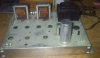
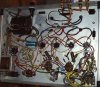
Made some great progress on the amp , competed the voltage buck, a switchable 6n2p pre with volume pot, variable feedback, and balance mod. Have some cosmetics and minor details but it came out very nice and the sound is amazing.
 

Attachments

  • before.jpg
    before.jpg
    30.7 KB · Views: 79
  • after.jpg
    after.jpg
    52.8 KB · Views: 128
  • undrr.jpg
    undrr.jpg
    87.7 KB · Views: 106
Looks excellent. Good work.
My finished 9302 just left to my sisters house yesterday eve after we listened to it all day.
It sounded great too

Fun hobby. On to the next chassis.
 
Back
Top Bottom