• The move to the new server is done. There are some software and database maintenance updates in process. This has us passing the hat around to help out. We appreciate any donations. Seriously, even a dollar helps. The payment page may be found here - https://www.audiokarma.org/support.html

Another Maggy Thread

Nice work!

That amp is looking nice Roggom! Did you do that sand and then buff method to the aluminum?

I don't really have a good answer on the cap question from a few posts up. I tend to order a few values of everything so I can tweak if I ever get around to it.

If you have a schematic of your mods I would love to look at it.


Say, Resound, what is that cool amp with the VM logo? I am totally going to make my next speaker box retro themed.:thmbsp:

Dan
 
Thanks, but be sure that the unused heater winding is in fact isolated, and there's no centertap or such connected to ground or something else inside the amp. Then you should be good to go.

I tried this on my 9302 and it just popped the fuse. There is a center tap connected to ground though as you mentioned. Any workarounds for this?

This would be a good mod for all my chassis at my house. My walls show 123v
 
Say, Resound, what is that cool amp with the VM logo? I am totally going to make my next speaker box retro themed.:thmbsp:
Dan

Hi, snuck in ahead of me I see.

Thats a Voice of Music Model 160 PA box. Its the coolest of all VM amps Id say. Little 10w 6V6 stand alone chassis inside pushing a Jensen p10R. They were made from 1949 to 1954. Ive got a complete unit as in the pic and Ive got a chasssis by itself that Ive bumped up to using 5881's and Ive got it pushing a Jensen P12P in an old AMPRO case.
Strictly guitar use though.

Oh yeah I have to ask you. Was that 9302 schemo I got from you a timed file? or limited distribution file?

I ask because Its nowhere to be found on my computer now. It has disappeared completely. If I accidently deleted it, it would be in the recycle bin that hasnt been emptied in months and its not.
A search brings up all PDF's but not it.
Very strange.

 
Ok, Thanks Kegger.. I think I'm gonna tear this baby apart and rebuild it per your schematic and suggestions. I even have the original 86xx transformer--I used it in a little guitar amp---that I may swap into the rebuild. That will give me a couple of mini-projects to keep me from spending money on another big project. (Although I do want to build the 93xx or the 6v6 amp sometime) Gotta luv Tubes! One more question for you or anyone, If I wanted a cathode resistor for each El84 would i use the same values for res. and bypass cap you suggested for both ( I am uncertain how to determine the cathode resistor) and also would the el84 cathodes still be tied together as they are with a shared cathode resistor? Oops, that was 2 questions. Thanks again, Stan

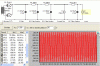
Ok, so the tranny i had was not from a 86xx, it is from a 196-xx. It is 300-0-300 w/ 5v and 6.3 taps. Really would like to use this in a supply for the 86xx mod. that Kegger posted. Is this tx gonna be too much? I have attached a power supply i did w/ PSUD2, would this work? Any suggestions/recommendations are welcome. Thanks, stan
 

Attachments

  • 86xx.jpg
    86xx.jpg
    91 KB · Views: 33
Yes that tranny should work, I would do something like this.

Remember you are doing 2 output tubes, so your first Current tap should be for
what 2 would draw and where your output transformer takes power, then that
second tap is what feeds the front end an your screens if your running pentode.

That first 6.5uf or so cap I would suggest a solen 630v poly cap. You can "TUNE"
the output voltage raising or lower that first cap, I'd use 6.5uf first, then paralell
others onto it to raise it from there. ;)

Also I would use a 5V4 rectifier instead of the 5Y3, as the 5V4 is slow warmump. :thmbsp:
 

Attachments

  • maggie_power_mod.GIF
    maggie_power_mod.GIF
    29.3 KB · Views: 45
Thanks Kegger, as you can tell I am still learning! I really appreciate your suggestions. I wish I had a local shop where I could pick up all the components I needed for amps, It suxs having to order and wait on everything. Gonna have to order some more caps and things so I am waiting again.. Thanks again, Stan
 
What I posted doesn't have to be "Just" like that nor will that be the defacto you end up
with, just a solid starting point, maybe you have parts that will get you close? If yu think
yu might try running other sims with the layout and currents I put in there, see if yu may
have some parts to get yu there?
 
That amp is looking nice Roggom! Did you do that sand and then buff method to the aluminum?

I don't really have a good answer on the cap question from a few posts up. I tend to order a few values of everything so I can tweak if I ever get around to it.

If you have a schematic of your mods I would love to look at it.
Dan

I used Eagle one Nevr-Dull and around 3 hours of polishing, the smell reminded me of when I was on ship in the Navy shining the brightwork.

I recently changed the 5u4 to a 5V4 (st type).
As far a caps, I found some Vitamin Q pio's at my local electronics shop and changed the coupling caps from .0015 to .0068 and .047 to .082, very nice improvement, tad more bass.
 
What I posted doesn't have to be "Just" like that nor will that be the defacto you end up
with, just a solid starting point, maybe you have parts that will get you close? If yu think
yu might try running other sims with the layout and currents I put in there, see if yu may
have some parts to get yu there?

I've got to order some parts no matter what, I was just complaining.:tears: I haven't built up much of a parts stash yet. Also,I want to get a couple of 5v4s-- I have always used 5y3 and 5u4s and need to try the 5v4and 5ar4 as you suggested in an earlier post. I will definitely play with the layout you suggested and probably breadboard it when i get some parts. ( my actuals are almost always higher than PSUD2 predicts) Thanks for getting me going w/ a good starting pt. Stan
 
Ahh I see, (For me actually PSUDII is really really close, using real world current draw)

I buy most of my parts in bulk off the bay, there are certain types of tubes I "generally"
use so I know what values I use most of so I search the bay for bulk, when I find what
I'm looking for I see what else the sellar has an stock up to save on shipping.

As of the last year or so I haven't really had to buy any passive parts, and most of the
iron I would need I have stocked up on as well, I would like to get a few more of Edcors
Single ended tranny's, I will be picking up some larger ones for a "funky" project. :)
 
86-01

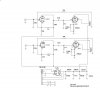
Ok, so i am playing around with a breadboarding of the modded 86-01 amp while i am waiting on some parts in the mail. I have built the p/s per the attached schematic. I know it is far from an optimal supply but it is best i can do with the parts on hand.The 300 resistor is 3 five watt ww in series to get 300R. The 200R is 3 in series also. Trouble is, it burns up the 1.5k resistor about 10 sec after i cut it on. I know the voltages will be off for what the circuit requires, but shouldn't the supply be alright temporarily? Should this supply work at all or do you think there is another reason for the resistor going bad, such as a wiring problem? Thanks
 

Attachments

  • maggie8601bb.jpg
    maggie8601bb.jpg
    53.6 KB · Views: 73
Ok, so the tranny i had was not from a 86xx, it is from a 196-xx. It is 300-0-300 w/ 5v and 6.3 taps. Really would like to use this in a supply for the 86xx mod. that Kegger posted. Is this tx gonna be too much? I have attached a power supply i did w/ PSUD2, would this work? Any suggestions/recommendations are welcome. Thanks, stan

Do you still happen to have the little one henrie choke that went with the 196-XX PS transformer and amplifier?

They are fairly common, I think I have couple lost in here somewhere....

If you can find the stock Magnavox 196-XX console amplifier schematic, you can copy the 5U4 (or use 5V4) power supply circuit part for part.
And you can still use Kegger's 8600 maggotbox modified circuit.

My 8600 amplifier uses the 196-XX front end circuit from the most simplified 196-XX version. (With the 6EU7) I think there is a couple few versions.
But it uses the original 6CA4 CRC supply.
A audio friend has a stock 196-XX Magnavox console amplifier. The amplifier was plenty quiet with the stock 5U4 power supply with the little 1 henrie choke.
He also used a 5V4 in place of the 5U4.

Maybe use a higher wattage 1.5K resistor, or see if you have voltage after the 1.5K resistor. If there is no voltage after the 1.5K resistor and the resistor is cooking, you may have a cap shorted, or short to ground.....I dunno....
 
Only thing that is coming up making sense is that maybe you have 150 ohm instead
of 150K ohm in the resistor feeding the cathode of the driver or other wiring issues.
(Also if replacing the 150K resistor, try getting it closer to 180K)

That 1.5k for your supply resistor should be seeing less than 1/10 of a watt there!
(In other words no reason to burn up in this setting when properly wired)

Power supply, in your config your probably a bit high, a good tweek to what u have
would be a nice little poly or oil cap of say between 3-5uf in place of the first 22uf.

Ok, so i am playing around with a breadboarding of the modded 86-01 amp while i am waiting on some parts in the mail. I have built the p/s per the attached schematic. I know it is far from an optimal supply but it is best i can do with the parts on hand.The 300 resistor is 3 five watt ww in series to get 300R. The 200R is 3 in series also. Trouble is, it burns up the 1.5k resistor about 10 sec after i cut it on. I know the voltages will be off for what the circuit requires, but shouldn't the supply be alright temporarily? Should this supply work at all or do you think there is another reason for the resistor going bad, such as a wiring problem? Thanks
 
Silly question

Ok, so i am playing around with a breadboarding of the modded 86-01 amp while i am waiting on some parts in the mail. I have built the p/s per the attached schematic. I know it is far from an optimal supply but it is best i can do with the parts on hand.The 300 resistor is 3 five watt ww in series to get 300R. The 200R is 3 in series also. Trouble is, it burns up the 1.5k resistor about 10 sec after i cut it on. I know the voltages will be off for what the circuit requires, but shouldn't the supply be alright temporarily? Should this supply work at all or do you think there is another reason for the resistor going bad, such as a wiring problem? Thanks

Silly question,

Do you have the rest of the circuit you showed connected to your power supply? Or is it just the PS on the breadboard?

I dunno if it matters, but I wondered after reading your post if you had a load.


Dan
 
I have the whole circuit wired up---it is a birdnest for sure. Something is not wired right because I have tried other caps in the supply and a 4.7k resistor in place of the 1.5k and it flamed up too. Don't really have time to check any voltages because the res. burns up in about 5 secs. Guess I'll re-do everything.... I basically breadboarded the circuit to test various power supply schemes. Thanks for the help, Stan
 
I have the whole circuit wired up---it is a birdnest for sure. Something is not wired right because I have tried other caps in the supply and a 4.7k resistor in place of the 1.5k and it flamed up too. Don't really have time to check any voltages because the res. burns up in about 5 secs. Guess I'll re-do everything.... I basically breadboarded the circuit to test various power supply schemes. Thanks for the help, Stan

check out all your solder joints . .. I had a resistor lead grounding out and had a hell of a time treacking it down . . it almost always turns out to be something simple :thmbsp:
 
hmm

Think of all the great experience you will get troubleshooting!

Is there anyone else who can check you work? Sometimes a second set of eyes can help.

Programmers will read their code to someone else, even someone who does not understand and sometimes it helps them think about it again.

There is the thing I do where if I decide a certain part of a circuit or whatever is correct. It will always stay correct untill I revisit it with fresh eyes!

I did that to a ground wire once and another tech had to drive 100 miles to be the fresh eyes. he was like, you left a ground loose, and I KNEW it was loose and had decided it was ok. LoL

Good luck

Dan
 
What's going on????

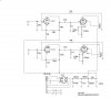
Ok, so i received all my parts and built the modded 8601 per the attached schematic. I used completely seperate components than what i used on the breadboard. The last resistor in the power supply (2.5k/2w) fries after about 5 secs.---- same thing that was happening when i breadboarded the amp. (although p/s was different in breadboard than final build---see previous posts) Any ideas what the problem is??
 

Attachments

  • maggie8601.jpg
    maggie8601.jpg
    53.7 KB · Views: 70
Well I went over the audio circuit schem, that all does look fine and the same thing I am
running here but pentode instead of UL, but that won't make any difference here though.
(Just FYI, I have changed the feedback resistor to 20K now though from the 39K)

I have been running this for at least a month or 2 now, sounds great works great, for the
past couple weeks the amp has been on 8 hours a day 7 days a week while I am building
some high sensitivity speakers.

Your Power Supply should be good as configured also.

Here's some things to try:

Check all the tubes with a tube tester or replace with known "other" good ones.

Disconnect the supply from feeding the front end, power the amp up and test all your
output section voltages and whatnot, see if the 2.7k resistor stays intact.

(MEASURE) all your resistors in the front end, they may be marked wrong, I've seen it
before where there marked one thing, but actually read something completely different.

You may have a bad socket up front on the driver tubes.

Power the amp up with no driver tubes in place, see if the 2.7k resistor blows, if it does
then you have a wiring, socket or resistor value error up front in the amp.

You are using 6EU7 and not 12AX7 right? (As the schem is wired for 6EU7)
 
Thanks for the response, Kegger. I will try all of what you suggested sometime this weekend and post results. Seems strange that I am having same problem with the build as i did on the breadboard. (using all different components except transformers and tubes) I have built at least 3 of the 86-xx circuits in the past w/ no problems so it not completely new to me. Oh well! the P/T came from a maggie 196 or 197 and I am using seperate cathode resistor/cap, niether of which should be a problem. Thanks, Stan
 
Back
Top Bottom