• The move to the new server is done. There are some software and database maintenance updates in process. This has us passing the hat around to help out. We appreciate any donations. Seriously, even a dollar helps. The payment page may be found here - https://www.audiokarma.org/support.html

Another Restoration, 9090 non DB receiver

Kale

Super Member
OK, I just finished one big restoration on Sansui 9090 (non DB) receiver. I am going to show you so many interesting pictures at that thread… so….

As you probably already know, 9090 receiver has quasi- complementary power stage with 8 pieces Sansken 2SC1116 TO3 NPN transistors, so it is not the same as 9090DB which has complementary output stage with 4 PNP and 4 NPN TO3 transistors.

Receiver was in good shape, but not so clean, and with big problems with contacts on potentiometers and switches and selectors.

PICT1409_zps455c90f3.jpg


… power supply board and driver board…

pict1410_zps76c0ee1d.jpg


… phono preamp…

pict1411_zpsbf8ae9ef.jpg


… driver board pulled out…

PICT1419_zps4629efeb.jpg


… another side of the driver board… I know that it will be a lot of work on that board… but about that, later…

PICT1420_zpsdf2e1cbf.jpg
 
Register to hide this ad
So, let’s get started dismounting receiver…

PICT1428_zpsbd588f65.jpg


I like to protect knobs against damage, so every knob was at separate small plastic bag..

PICT1430_zps292af5b1.jpg


… And finally, “naked” receiver…

PICT1431_zpsa598f386.jpg
 
First board, on which I started restoration was Phono Board with input selector… because it was very dirty, I have to dismount almost everything to clean those parts properly

pict1432_zps76723a14.jpg


… first Input Selector…

pict1433_zps039379a9.jpg


pict1434_zpsce010241.jpg


… and cleaned…

PICT1438_zps0f5c9e84.jpg


… then, Tape Selector…

PICT1439_zps50bb69a4.jpg


… and cleaned…

PICT1441_zps0953adc2.jpg


… another cleaned side…

PICT1442_zpscaf953fe.jpg
 
BUT we will go back on the picture of Input Selector…
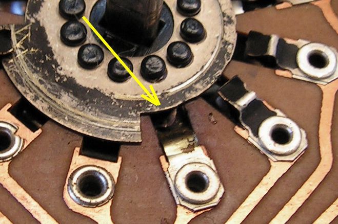
Do you see anything wrong here?

pict1433_zps039379a9.jpg


No? OK, please look at that detail…

pict1433__zpsd3c6a18a.jpg


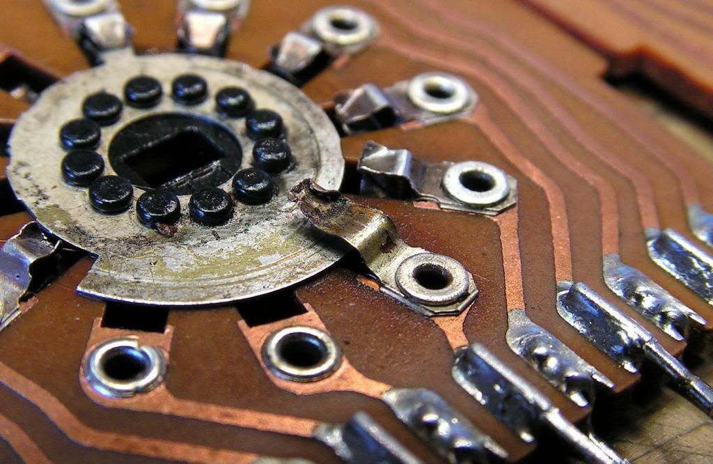
That contact was bent!!! I really donz know how?!? I tried to fix it, but without good result!

PICT1436_zpsbf3e919d.jpg


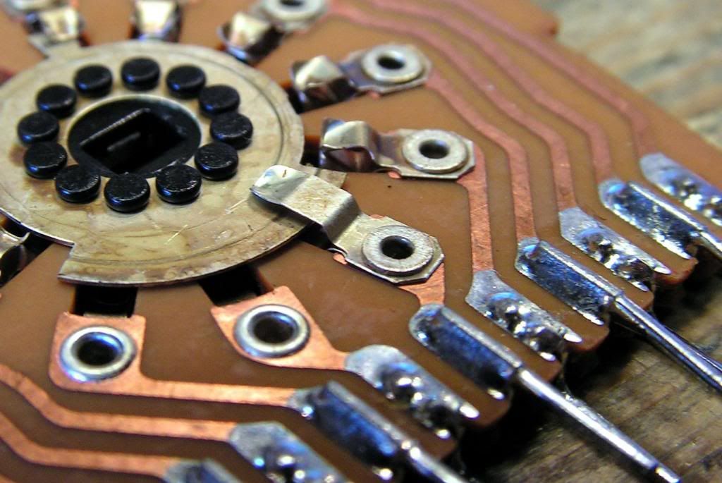
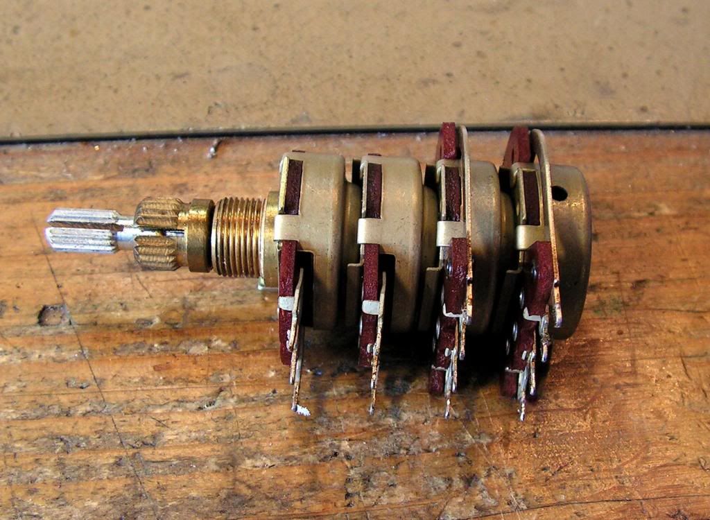
… and, I was lucky… at my stock I had a NOS input selector, so I replaced that wafer (not all selector, just that wafer)

PICT1437_zps16a14bb2.jpg


And that first board was restored…

PICT1445_zpsa85fd51e.jpg


PICT1446_zps5a49f9e5.jpg


Normally, I resoldered every solder point, and covered with new layer of colophony (rosin).
 
And now, the Power Supply Board…

PICT1422_zps744162bc.jpg


… another side…

PICT1447_zpsfa668de6.jpg


Those fuses should be replaced because I think they are old car fuses, I would replace them by ceramic 10A fuses

PICT1443_zps3d446e8b.jpg


… there, I had a problem with that 1000uF capacitor. It was with three legs, and new one what I have is smaller and with two legs…

PICT1462_zps0297ef61.jpg


PICT1461_zps6c8862e1.jpg


So, I made a new solder point for that new smaller two contact 1000uF capacitor

PICT1463_zpsbf129bdd.jpg


PICT1464_zpsd9034c20.jpg


… and the result is here…

PICT1465_zps065b4f65.jpg


PICT1466_zps51935d2e.jpg
 
And, here they are 8 pieces of Sanken 2SC1116 transistors…

PICT1456_zps8b20eaf3.jpg


I must dismount all because I must clean all those parts…

PICT1457_zpsd18a5187.jpg


And finally TO3 sockets….

PICT1458_zps950cb0f4.jpg
 
Wow guys! I just started, I cant finish that thread today, because I have not so much free time to do this today, so, maybe it will be finished tomorrow.
Thank you for nice comments!
 
Obviously he knows his technical in's & outs... But you have SO MANY repair people called TECH's.. And half em don't know what end of an iron to hold... Only the really really REALLY good ones would even attempt a wafer switch repair...on a component level... I've tried a few times and made a dogs breakfast outta em. My point is there are so few that do this level of "QUALITY" of "CRAFTSMANSHIP"...I applaud this work... I repair things... he restores things to better than new.. from what I see.
 
Thank you vigman, but I just have time to do this on that way, so prof tech cant do this like me, because he is working for his life, I am not, I am working this because I like it, and that is the different between me and prof tech.
 
Let's continue…

That power board is, on the same time, the mother board for driver board, so it had some burned damage from the past, and it was not fixed nicely, so I tried fix that damage on better way… not excellent, but just better way… so how it was:

PICT1482_zpsbbdb3b31.jpg


And how it is now…

PICT1483_zps59352670.jpg


… those bipolar capacitors that were soldered on the back side of that board (probably because they will be in touch with those ceramic emitter resistors… heat problem) I soldered back on component side, because my bipolar capacitors are smaller than those older.

PICT1485_zps99c271e0.jpg


And you can see them just beside of connector for driver board

PICT1488_zps36382556.jpg


As you can see, another one is done…

Next tomorrow...
 
Last edited:
Kale,
Thank you for sharing all this... it kicks me in the ass to do a better job... I just retired, so like you.. I will have time for the detail work... I'm stuck on a B & B systems audio phase scope.. right now.( if I can't make a breakthrough... re assemble and store in the garage ).. Then back to my AU-9900 and the AU-717 ( TRYING to find a volume control ) AU-D7 minor bias problem.... once that is done.. I have a 9090 hiding in the closet ( for 8 years ) .......
Mike
 
Fantastic Job Kale. Gives me some belief my 9090 can rise phoenix like from the ashes. Hopefully I'm right (downthe road.)

Larry
 
:d

Kale,
Thank you for sharing all this... it kicks me in the ass to do a better job... I just retired, so like you.. I will have time for the detail work... I'm stuck on a B & B systems audio phase scope.. right now.( if I can't make a breakthrough... re assemble and store in the garage ).. Then back to my AU-9900 and the AU-717 ( TRYING to find a volume control ) AU-D7 minor bias problem.... once that is done.. I have a 9090 hiding in the closet ( for 8 years ) .......
Mike

Mike, I am still working, I am not retired. but I have some specific professional working time that I can, from time to time, work on Sansuies.
The average time for finish one receiver like this, is from month and half to 2 months. Because of that, I can do restorations on four to max, 5 units per year. sometime just three units per year (for example if I am working on AUX1)...
 
Now, we are going to the front of the receiver…

PICT1495_zps39658169.jpg


First job what I will do is deep cleaning of volume - balance potentiometer, because it had a big problem with bad contacts…

PICT1495_1_zps5638cd43.jpg


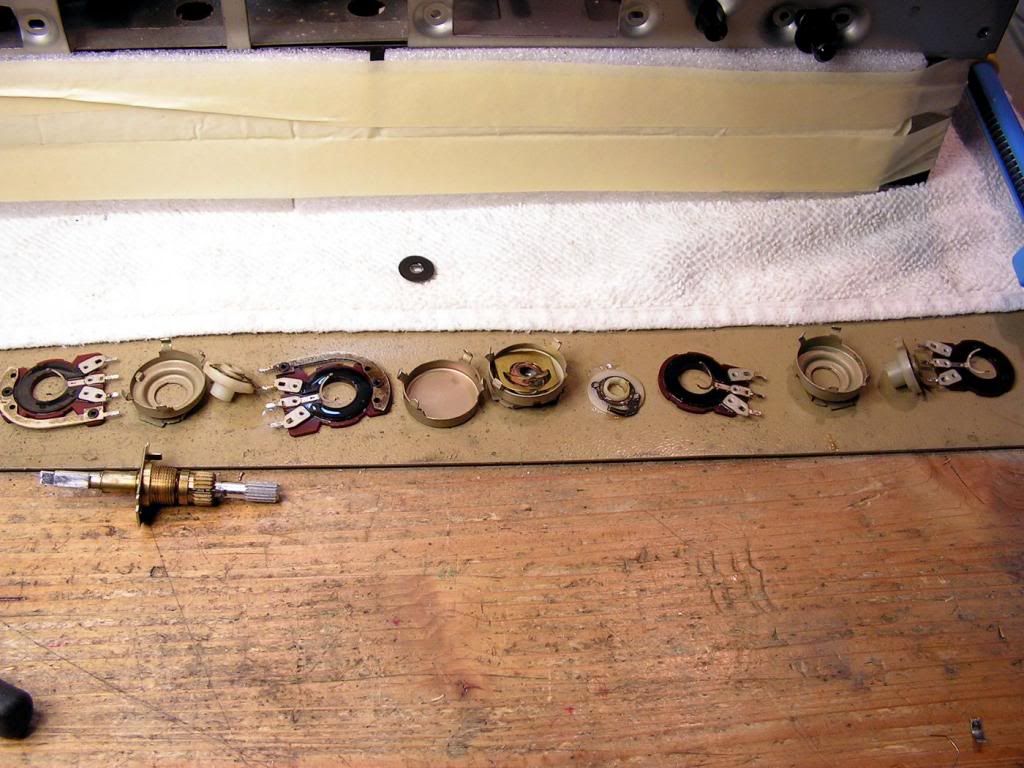
It is not easy to dismount, but finally on the next picture you can see all parts of that potentiometer

PICT1495_2_zps206d89cb.jpg


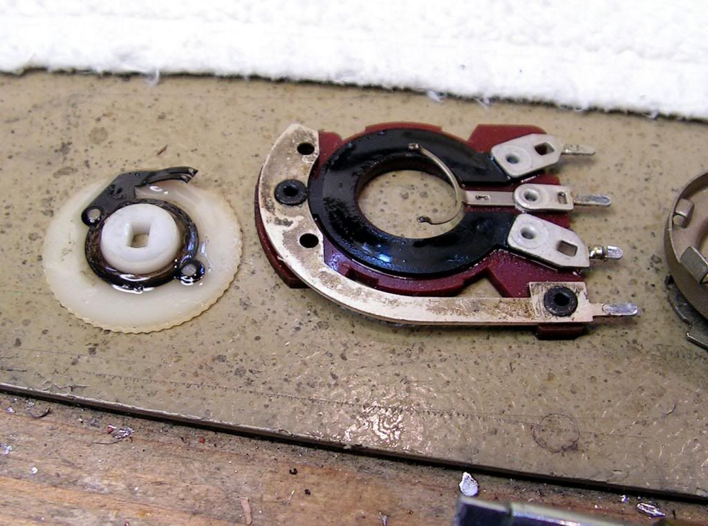
… and please look how dirty it was….

PICT1495_3_zpsbecd41d4.jpg


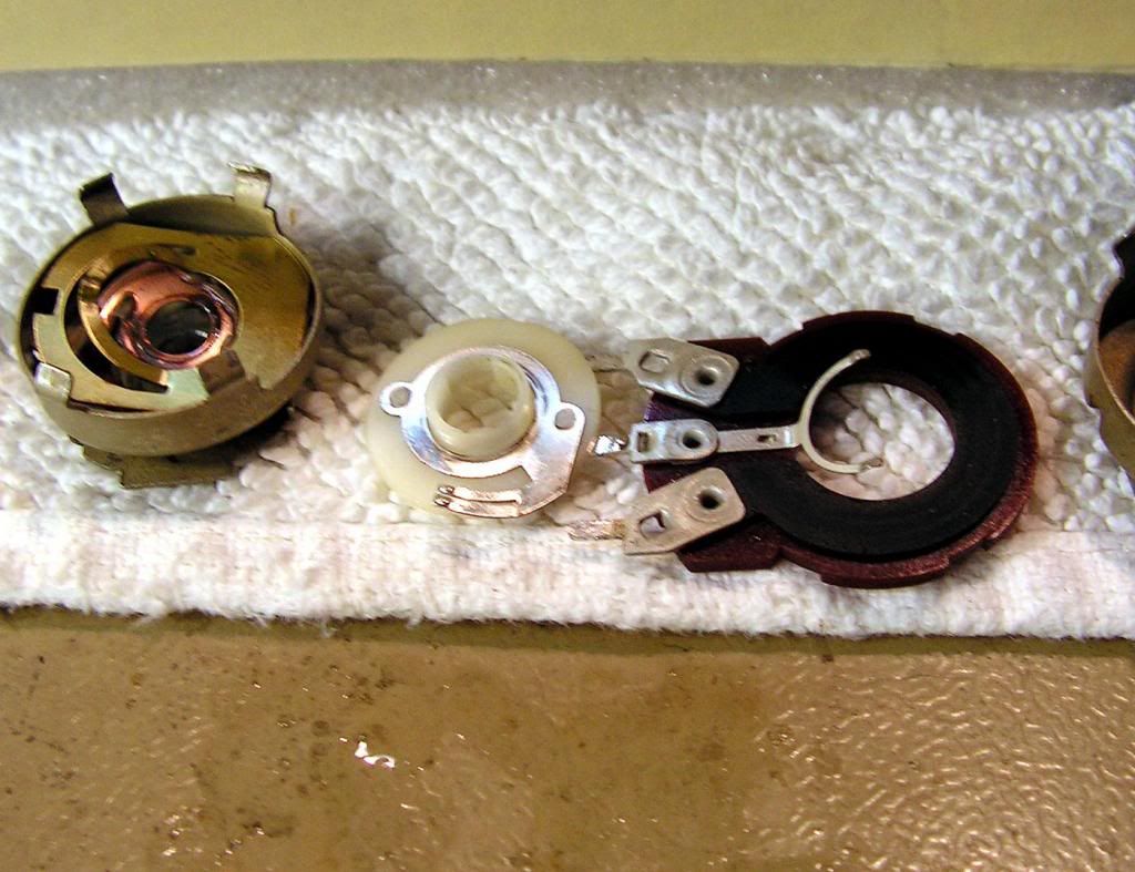
… and after cleaning…

PICT1495_4_zps4c9b3ca7.jpg


The same thing with switches…

PICT1501_zpse4865924.jpg


PICT1501_2_zpse6fead21.jpg


… close view…

PICT1501_3_zps19ac3e3d.jpg


Another dirty switch…

PICT1501_6_zpsbce24cb9.jpg


And how I cleaned them….

PICT1501_1_zps480b897b.jpg


PICT1501_4_zps8312d085.jpg


PICT1501_9_zps3edbc4a8.jpg
 
Back
Top Bottom