• The move to the new server is done. There are some software and database maintenance updates in process. This has us passing the hat around to help out. We appreciate any donations. Seriously, even a dollar helps. The payment page may be found here - https://www.audiokarma.org/support.html

(another)Yamaha C-70 Project

sonavor

Active Member
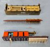
It has been a year now since I updated my own Yamaha C-70 with a nice replacement relay switch part for SW503 (Parametric Tone Control on/off) from Kurt Jacobs. The C-70 is still working great and I use it everyday in my office.

A fellow C-70 owner who lives fairly close to me contacted me, also about a year ago, to see if I could fix the SW503 switch in his unit. Along with that Parametric Tone Control switch replacement he would like me to look over the C-70 to see if there are any other updates he would like to make.

This C-70 has already been recapped so tomorrow I will open it up and look at the condition inside.

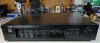
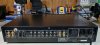
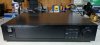
To start off this post here are some photos of the outside.
 
Register to hide this ad
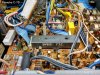
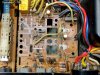
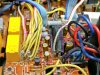
I removed the top and bottom covers of the Yamaha C-70

c-70_j01_first_opened_up_01.jpg

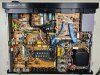
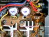
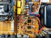
I was glad to see the person that performed the electrolytic capacitor replacement did a nice jobs.

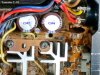
The old glue for capacitors C596 and C597 was all cleaned up and gone. They also used some nice Nichicon and Elna capacitors.

c-70_j01_first_opened_up_02.jpg c-70_j01_first_opened_up_03.jpg
 
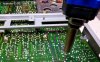
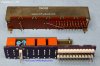
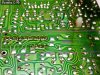
When I removed the SW503 switch....Hello F.O.D. problem

c-70_j01_sw503_03.jpg

This is most likely a result of Murphy's Law. You know the one where if you drop something small it will disappear from view and land it some remote place where it can cause a problem.

But seriously, when clipping the leads off newly installed components, like capacitors, you have to be wary of the excess lead part flying off somewhere.
In this case the lead had become magnetized and was shorting a couple of the switch leads.
 
C590 is and 85° cap. I would move it to the other side of the PCB away from the transformer and heatsink heat.
index.php
 
Yeah, that area is where the C-70 really heats up. I was thinking about whether I would change anything about the recapping job. On my C-70 I installed 105°C capacitors. I might have some in stock. Moving the caps to the opposite side is a good thought. I hadn't thought about that.
Thanks.
 
On my C-70 I installed 105°C capacitors.
No room for C597 and 596 on the backside. So you have to go with 105° or higher. C590 I used a Nichicon PW( 105°) mounted on the solder side.

BTW that jumper wire beneath C590 in your photo looks oxidized.
 
Thanks to Eagle Eye I re-examined the power supply of this C-70. I do have to do some rework in here.
The person that originally recapped this preamplifier chose good quality capacitors but us C-70 owners know that the area around the power supply gets very hot when the amplifier is on. Yamaha also put vents in the metal cabinet over this area.

The two 1000uF capacitors, C596 and C597, are okay. They are rated at 105°C. The rest of the nearby electrolytic capacitors are Nichicon audio capacitors and are rated at 85°C. While those will work okay it is better to change to at least 105°C rated capacitors in the C-70 power supply area...just as a little more insurance for longer life in this application. There is also a corroded jumper wire and some other components that I need to check the leads (for corrosion) on.
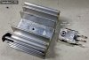
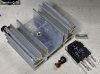
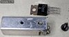
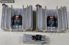
The transistor thermal paste on the three heatsink mounted transistors (TR536, TR542 and TR547) look completely dried out so I will clean them up and add new thermal paste.

c-70_j01_pwr_sply_01.jpg c-70_j01_pwr_sply_02.jpg c-70_j01_pwr_sply_03.jpg
 
After cleaning up the power supply area it looks like just two resistors, R670 and R671, would probably be better to replace. They measure within their 18KΩ tolerance but I couldn't get the corrosive tarnish off them as I would like to. The originals are carbon film resistors so I will replace them with the same kind. Unfortunately I don't have those in stock so I ordered them from Mouser. That should take a day so I should have them by Tuesday.

Here is the power supply area all cleaned up. I installed a new jumper wire and reworked the thermal paste on TR536, TR542 and TR547.

c-70_j01_pwr_sply_08.jpg

c-70_j01_pwr_sply_04.jpg c-70_j01_pwr_sply_05.jpg c-70_j01_pwr_sply_06.jpg c-70_j01_pwr_sply_07.jpg
 
Back
Top Bottom