You are using an out of date browser. It may not display this or other websites correctly.
You should upgrade or use an alternative browser.
You should upgrade or use an alternative browser.
(another)Yamaha C-70 Project
- Thread starter sonavor
- Start date

This your C-70 ?looking good.....guess a experienced C70 guy beats a regular ol repair guy any day
 C-70 is a most excellent control amplifier. One of my most favorites.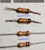
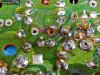

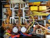
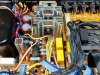
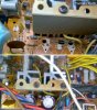
Perhaps I can find a substitute material to replace this with.
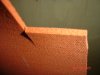
I use this red silicone,closed cell, sponge foam approx. 4.5mm(3/16") thick.wedged between the heatsink and capacitors
https://www.mcmaster.com/sponge-rubber/color~red/texture~crisscross/thickness~0-1875inches/
Last edited:


sonavor
Active Member
The High-Temperature Silicone Foam Sheets and Strips that Avionic suggested looks good.
I also started looking at these three different products -
Tflex HR400 Series Thermal Gap Filler
3M™ Flame Barrier FRB-NC Series
SWITCH INSULATOR FISH PAPER
I might order some of those as well to compare.
I also started looking at these three different products -
Tflex HR400 Series Thermal Gap Filler
3M™ Flame Barrier FRB-NC Series
SWITCH INSULATOR FISH PAPER
I might order some of those as well to compare.

That HR400 thermal gap filler is actually a heat conducting material, so I wouldn't use it as a thermal insulation.
Cheers,
James
Cheers,
James
sonavor
Active Member
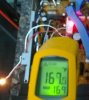
Moving on to the Yamaha C-70's power on lamp in the on/off switch, I discovered on my own C-70 project that quite a bit of wasted heat exists inside the C-70 from load resistor for the power on lamp. Make no mistake though, most of the heat comes from the two transistors : TR542 and TR547. Those do and will continue to put out a lot of heat out the C-70 case vents. It just doesn't help that the R860 load resistor for the power on lamp generates 160 + degree fahrenheit of heat. This picture isn't the best but it shows what R860 measures (with the case open) when the C-70 power is on. This photo is from my C-70.
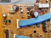
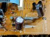
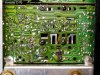
Here is what the area around R860 looks like on this C-70 project. You can see how darkened the PCB is from the heat coming off R860.
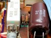
The photo also shows that there is still residue from the old glue Yamaha used to secure the larger capacitors.
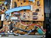
I am going to clean up the rest of that old glue residue, replace any components with corroded contacts and I will replace the C-70 original power on lamp with an LED that will be powered by the C-70's +15VDC supply.
Here is what the area around R860 looks like on this C-70 project. You can see how darkened the PCB is from the heat coming off R860.
The photo also shows that there is still residue from the old glue Yamaha used to secure the larger capacitors.
I am going to clean up the rest of that old glue residue, replace any components with corroded contacts and I will replace the C-70 original power on lamp with an LED that will be powered by the C-70's +15VDC supply.
sonavor
Active Member
To restate the problem with the original power on lamp, here are some pictures.
The C-70 power on lamp gets power directly from the AC voltage coming in the C-70's power transformer. Yamaha ran two wires for the power on lamp (a 14.5V, 80mA lamp) with the R860 load resistor (390Ω) as shown in the schematic diagram.
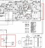
The actual circuit includes additional 8.2KΩ and 12KΩ resistors in parallel with the 390Ω resistor. Nothing else uses this circuit except the power on lamp and as can be seen by the darkened PCB (and as I measured) there is a lot of heat being dissipated by R860.
Here is the service manual board diagram. It does show the additional two parallel resistors.
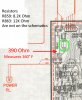
What I did on my own C-70 and what I will do here is to remove the original power on lamp. That means no current will flow through R860 (and the two parallel resistors) so it will remove that heat source.
The C-70 power on lamp gets power directly from the AC voltage coming in the C-70's power transformer. Yamaha ran two wires for the power on lamp (a 14.5V, 80mA lamp) with the R860 load resistor (390Ω) as shown in the schematic diagram.
The actual circuit includes additional 8.2KΩ and 12KΩ resistors in parallel with the 390Ω resistor. Nothing else uses this circuit except the power on lamp and as can be seen by the darkened PCB (and as I measured) there is a lot of heat being dissipated by R860.
Here is the service manual board diagram. It does show the additional two parallel resistors.
What I did on my own C-70 and what I will do here is to remove the original power on lamp. That means no current will flow through R860 (and the two parallel resistors) so it will remove that heat source.