• The move to the new server is done. There are some software and database maintenance updates in process. This has us passing the hat around to help out. We appreciate any donations. Seriously, even a dollar helps. The payment page may be found here - https://www.audiokarma.org/support.html

(another)Yamaha C-70 Project

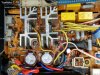
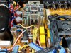
I am sorry for being persistent, but the white wire from the TC2 power supply tells us something. Feel free to compare the two pictures attached. Look carefully at the left fron corner of the heatsink and the white cable. The first image was taken earlier, the other one later, after the fuse was blown. Am I the only one you can see it? Is it so hard to admit a mistake? Something like this happens to everyone working on vintage hifi, me too.
 

Attachments

  • c-70_j01_pwr_sply_10.jpg
    c-70_j01_pwr_sply_10.jpg
    173 KB · Views: 78
  • c-70_j01_pwr_sply_F501_01-1.jpg
    c-70_j01_pwr_sply_F501_01-1.jpg
    163 KB · Views: 75
Hi Dr. Ear,

I think that image that you are seeing as a bare strand of silver wire is just a reflection in the photo. I had checked all of the power supply connections very thoroughly when I finished and first powered the C-70 on.

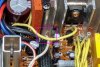
Here is a better angle of that terminal with the white wire. You can see that it is not as close to the heatsink as the other angle makes it appear. Plus, the wire is a solid wire for the wire wrapping so there really isn't a loose strand.

I will continue this current burn in test with the new rectifier then put the cabinet covers back on and run it continuously for another day.

c-70_j01_pwr_sply_09.jpg
 
I am sorry for being persistent, but the white wire from the TC2 power supply tells us something. Feel free to compare the two pictures attached. Look carefully at the left fron corner of the heatsink and the white cable. The first image was taken earlier, the other one later, after the fuse was blown. Am I the only one you can see it? Is it so hard to admit a mistake? Something like this happens to everyone working on vintage hifi, me too.

Yes, I have had my fair share of "oops" moments. I share your concern about why the rectifier device failed but I haven't been able to find a source for that yet.
As I just posted, those wire wrap terminals are tight and don't have any wires that could touch the "live" heatsinks. I am also not a fan of those wire wrap terminals but Yamaha seemed to like them at the time (just look at the M-70).

Again, here is a closeup of the area you thought you were seeing a stray strand of wire. What you are looking at is the white, printed lines on the C-70 PCB and a reflection of part of it in the heatsink. The wires on the binding posts are solid wires and not stranded.
c-70_j01_pwr_sply_false_wire_appearance_01.jpg

I think all I can do at this point is continue with a thorough power on test of the C-70.
 
Last edited:
Here is the completed power on lamp replacement.

View attachment 1875603 View attachment 1875604

It looks pretty good.
Now I can reassemble the C-70, add the heat shied material to the power supply heatsinks and start testing this preamplifier.

Possible threadcrap! But I want to get around to getting an LED installed on my B&O 8002 turntable(s?) that shines across the disc in such a way that makes it easy to see and cue up tracks.
I've managed to ignore two PX-2 restorations and 3 (4?) 8000/8002s until COVID knocked me off that perch. The PX-2s are ready to go now, but motivating myself on the Bang & Olufsens may be more difficult:)
 
The lamp in the fixed arm of the Beogram 8002 (and their BG400x, BG8000 turntables) serve as light sources for an optical sensor that detects if a record is on the platter. An empty platter produces a pulse signal that the circuit used in reading the sensor reads.
That is important because the lamp type and angle it is installed affect the quality of the pulse signal. Beolover on the Beolover Blog makes a replacement LED replacement for the BG 400x series turntables. Unfortunately that won't work for the Beogram 8002. I wouldn't mess with changing the fixed arm lamp of the Beogram 8002. Just use a small LED flashlight :-)
In any case, if you have B&O turntable questions ask me through the Beolover Blog.
 
Sonavor-Yes, that is old and understood!
I'll have to play with a small LED on a cord to find where to mount it to the vertical wall of the tonearm bay so that it shows the bands best, and I'll need to leave enough excess harness so I can put the deck into the "service position". Not easily finding record tracks on the 8002s is about the only thing one could want regarding ergonomics on these decks. Otherwise, they are so nice to use. I realize making a hole for it and installing it may hurt it's value to the effete vintage snobs, but it's utility far outweighs the downside.

And, closer to topic, I always wonder about recapping and going over my CX2 preamp, but I think in the long game (selling time), I'm 73, leaving it un-molested may enhance it's value as well as suit my slovenly ways :)
 
Back to this C-70.

After replacing the bridge rectifier the C-70 played music continuously for just over ten hours with the top and bottom covers removed. That was so I could check it periodically for any problems.

There were no problems so I moved on and put the C-70 cabinet back together. After that I ran the C-70 for over twenty-four hours continuously playing music. It passed without any incidents.

c-70_j01_power_on_burnin_test_01.jpg

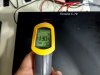
As with my own C-70, the metal cabinet section directly over the heatsinks gets to around 130°F. I have seen it up to 135°F.
That is the way these preamplifiers roll. Don't stack anything on top of the C-70 and don't place it inside a cabinet unless you have some sort of cooling fan on it. Years ago when my main system was a C-70 and an M-70 I had them in a pretty large cabinet but I had cooling fans on both amplifiers.

c-70_j01_power_on_burnin_test_02.jpg

This C-70 is ready to return to its owner again.
 
Thanks all for great info.
My SW 503 will not energize, so besides the switch itself ( have a new one in my hand from Ken) is there something else in that path to check besides the actual rocker switch? Is it using 16v to energize?
Have the service manual, low res it’s kinda hard to see even on 30” monitor.
 
Personally I'd upgrade that switch..

index.php
 
Before you commence. Measure the coil connection of the OEM 503 and toggle the front panel switch. To see if your getting the operating voltage to the switch.Looks like it should toggle between the +15vdc to -15vdc ballpark.
 
Last edited:
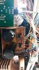
Seeking advice on repair of the solenoid switch SW-104

View attachment 2847180
Unfortunately, I disassembled and cleaned the SW-104 switch assembly years ago, before I did the full restoration of my C-70.
I didn't take any photos at the time but it wasn't too difficult of a task. Just take your time and go slow during the disassembly.
If you do the disassembly, take plenty of pictures every step of the way and post them on a new C-70 thread here. That would be helpful.

However...before going through all of that I would double check that SW-104 is a problem.

-sonavor
 
Back
Top Bottom