• The move to the new server is done. There are some software and database maintenance updates in process. This has us passing the hat around to help out. We appreciate any donations. Seriously, even a dollar helps. The payment page may be found here - https://www.audiokarma.org/support.html

(another)Yamaha C-70 Project

Okay, I got the rest of the service manual General Adjustments made (for the DC offsets).
I am stuck on Step 6 now : Gain Adjustment Equalizer circuit board. It says to use a 150mV input so I take that to mean a 1KHz, 150mVrms sine wave into a source input (like Aux 1). Then measure the normal Pre-Out jacks for 1.5V ± 0.5dB. But at what volume level?
If channel balance is OK you don‘t need to bother with this step.
 
Okay, thanks for that information. However, I already setup for it and want to document it so I can reference the next time.
I know I made these measurements on my own C-70 but that was a few years ago and apparently I didn't save my notes.

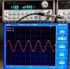
Here is the test setup for the C-70 service manual General Adjustments Step 6 : Gain Adjustment Equalizer circuit board.
I applied a 150mVrms test signal, a 1KHz sine wave, to the C-70 AUX 1 inputs.

yamaha_c70_sm_gain_adjustment_input_setup_01.jpg

I turned the C-70 volume knob to full on then measured the outputs of C-70 at the non-inverting RCA jacks.

yamaha_c70_sm_gain_adjustment_Lch_01.jpg yamaha_c70_sm_gain_adjustment_Rch_01.jpg

The left channel was right on the expected 1.5Vrms voltage. The right channel was close at 1.48Vrms and that is within the 0.5dB tolerance.
I am going to declare the service manual adjustments of this C-70 as completed and a Pass.
 
Those Agilents are not cheap either..My military test station was loaded with HP/Agilent test equipment for testing threat radar detection and jamming " black boxes" ie. ECM/EW.
 
Last edited:
Tonight I hooked up the Yamaha C-70 to a QuantAsylum QA401 Audio Analyzer for some performances tests.

I like using the QA401 quite a bit. I started out with their original QA400 then migrated to this new model for a slew of new features they added.
I use the QA401 to measure and check my audio projects hopefully in a consistent way so I can compare my results to each other. This is an ongoing process as I am learning as I go. It is a great way to check if anything odd is going on with one channel over another. I also don't kid myself that I can compare my test results with the original manufacturer's test results (i.e. their published specs). My equipment and test setup is quite different from theirs (it has been thirty to forty years in most cases).

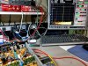
With that understanding here is my test setup for this Yamaha C-70. These preamplifiers are fairly easy. Unlike power amplifiers I don't have to deal with dummy speaker loads and high output voltages. The QA401 Audio Analyzer has Left and Right channel output stimulus signals as well as Left and Right input measurement signals.
The analyzer is USB driven and uses the Quant Asylum measurement software to run the tests.

Here is my test setup.
c-70_j01_performance_measurements_01.jpg

I won't show measurements on all of the C-70 source inputs. I also don't own a moving coil phono cartridge so that part of the amplifier I can't test.
Here is a typical set of tests I like to run. For these I will use the AUX 1 input and the non-inverting preamplifier outputs for the measurements.

Since the last service manual adjustment was the C-70 gain I decided to start with the same stimulus and output volume to measure THD.
That is a 150mVrms sine wave at 1KHz into AUX 1. The C-70 volume control was set to its maximum.
Here is the QA401 measurement.

yamaha_c70_js_THD_aux_150mv_in_max_vol_out_01.jpg

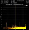
Next I ran a similar test except I wanted to check the THD with the C-70 at what Yamaha says its maximum output is, 10 Vrms.
So I upped the input level to use a 1Vrms 1KHz sine wave into AUX 1 and cranked the volume to maximum again.
yamaha_c70_js_THD_aux_1v_in_max_vol_out_01.jpg

Both THD measurements are very good on this amplifier.
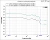
Next I decided to try a new QA401 frequency response measurement plugin. Quant Asylum releases a number of updates to their software and it often contains new measurement capabilities in the form of test plugins.
For this test I set the C-70 volume level to the halfway point and let the QA401 run its tests from 20Hz to 20KHz.
c-70_j01_performance_measurements_FR_01.jpg

From 20Hz to 20KHz the levels are only varying by 0.25 dBV. That looks quite good to me. I need to pull my own C-70 out of service and put it back on the bench for some measurements to compare to.

Now for the most important tests, the listening tests. That is where it counts the most.
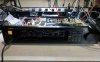
I connected up some Yamaha headphones and a turntable to check out how this C-70 Disc Direct sounds like.
c-70_j01_first_listening_test_01.jpg

That wraps up this project. As usual I come away with more knowledge about the audio component than before I started.

 
Last edited:
The joyful sound of this restored C-70 was short lived. The owner had to deliver the preamplifier back to me the next day as it would no longer power on.
It operated for a couple of hours then powered off.

Back at my workbench I quickly found that the 1A, 250V fuse, F501 had blown. I decided to try another fuse and it immediately blew when turning the C-70 on. So something obviously blew out. There are no visible signs other than the F501 fuse that anything is wrong.

On the next power on try I replaced F501 again but used my variac and dim bulb tester. Sure enough at less than 50 VAC applied with the variac the dim bulb tester illuminates and stays on. I shut everything down as I had my answer that something is shorting out.

Now I need to decide where to check next. I can check the transistors and diodes in the power supply circuitry but I am wondering if the transformer failed.
F501 is located between the power switch and one side of the transformer primary winding.

c-70_j01_pwr_sply_F501_01.jpg
 
Last edited:
The joyful sound of this restored C-70 was short lived. The owner had to deliver the preamplifier back to me the next day as it would no longer power on.
It operated for a couple of hours then powered off.

Back at my workbench I quickly found that the 1A, 250V fuse, F501 had blown. I decided to try another fuse and it immediately blew when turning the C-70 on. So something obviously blew out. There are no visible signs other than the F501 fuse that anything is wrong.

On the next power on try I replaced F501 again but used my variac and dim bulb tester. Sure enough at less than 50 VAC applied with the variac the dim bulb tester illuminates and stays on. I shut everything down as I had my answer that something is shorting out.

Now I need to decide where to check next. I can check the transistors and diodes in the power supply circuitry but I am wondering if the transformer failed.
F501 is located between the power switch and one side of the transformer primary winding.

View attachment 1880604
Is this a bare wire touching the heatsink (front left)?
 
No. I was wondering if something like that was happening too but after rechecking connections the problem is still there. That makes sense as well because the amplifier went through performance testing without any problems and nothing moved so I believe some component had to have failed.

c-70_j01_pwr_sply_02.jpg c-70_j01_pwr_sply_03.jpg
 
Check your bridged rectifier D521..It sits right next to the inboard 1000µf main cap. 4-pin SIP

index.php
 
Last edited:
but I am wondering if the transformer failed.
I doubt it.. But for your own satisfaction. The two pin connector right beside the bridged rectifier D521 is your power transformer blue and red secondary wires. Unsolder that connector. And check the transformer " unloaded ".. Probably 40 - 45 VAC between the blue wire and chassis ground. As well as the red wire and chassis ground. Maybe 80 VAC across the blue and the red wire.Its unloaded so the voltages will be higher than the schematic shows.
 
Eagle Eyed Avionic was right on about the C-70 full bridge rectifier (D521).

I pulled it out of the C-70 and measured its leads to each other. The minus lead was shorting. I had a spare D521 1B4B41 rectifier from a C-70 parts unit to swap out for. All four of its leads measure as you would expect using the diode tester of my DMM.

c-70_j01_pwr_sply_D521_01.jpg c-70_j01_pwr_sply_D521_02.jpg

I didn't take any chances and used my variac with dim bulb tester to check the C-70 power on again. This time the variac can dial up to 120 VAC and the bulb stays off. The C-70 powers on again.

c-70_j01_dim_bulb_test_02.jpg c-70_j01_power_on_test_02.jpg

I am still a little concerned about the D521 rectifier failure. Was it just ready to go and finally failed? Or is there still something else causing the problem.
Before giving the C-70 right back to its owner this time...I will keep it to run some burn in tests on. I want to make sure it can operate for several hours without any incidents.

I also need to decide if I keep the spare D521 rectifier installed in this unit or do I purchase a brand new replacement rectifier. May something like this.
 
Rectifiers usually don’t pass away without any reason. There was a short causing this event. In your case it was the wire which has broken off the wire wrapping terminal.
 
I left the C-70 playing music through some headphones for ten hours (and still playing).
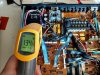
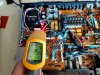
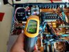
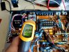
The cover and base of the cabinet have been off on this leg of the test but here is a look at how hot the power supply components get when power is on these units.

c-70_j01_tform_heat_check_01.jpg c-70_j01_TR536_heat_check_01.jpg c-70_j01_TR542_heat_check_01.jpg c-70_j01_TR547_heat_check_01.jpg

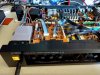
Here is the C-70 happily playing music again...at the ten hours mark.

c-70_j01_ten_hour_test_01.jpg
 
Back
Top Bottom