• The move to the new server is done. There are some software and database maintenance updates in process. This has us passing the hat around to help out. We appreciate any donations. Seriously, even a dollar helps. The payment page may be found here - https://www.audiokarma.org/support.html

Any Fi X3 300B amp owners out there?

Regarding the amp hum, the level might be slightly less after the resistor mod, but now the pot allows me to make it louder. Dowto1000, I am intrigued by your suggestion to try 6sl7 drivers. Garber shipped the X3 with 6sn7 tubes and I have many of these. Does the 6sl7 have the same current draw and operating voltage as the 6sn7 and can it be safely substituted for the latter? One of the many transformers on the X is probably for the filament. I have none of these tubes but could get a pair easily.
I also have not used this amp very much, only recently becoming interested in it after Don Garber’a passing.

- - - - - - - - - - - - - - - - -

You are sure the amp uses 6SN7s?? That is a mu of 20 tube ( mu is amplification factor ).

NO. You can not substitute a 6SL7 for a 6SN7, even though the tube Pin Out is identical. The 6SN7 operates at higher currents, and if Don designed the circuit for a 6SN7, you should NOT ever pop in a 6SL7 !! You will ruin it.

I can tell you this, ( IMHO, IME ) a good two stage DC amp with 2A3 finals loses MUCH of its sonic appeal whenever it loses a mu of 100 Driver tube. It will essentially sound DEAD, when using a mu of 20 driver tube, versus a mu of 100 tube, DCed to the 2A3.

This is NOT a question of overall amplifier gain, either tube, ( with a line stage / preamplifier ), will drive the finals OK.

No, it is that, at least to MY ears ( IMHO, IME ) , the mu of 100 tube is a much more livelier and a FUN sonic presentation for the listener.

The DC 2A3 amp with a low current / high mu ( 100 ) driver tube is so sensitive, that I get the feeling it, in ADVANCE, already "knows" what the next note or transient will be, and spits it out, with zero hesitation. This is so very amazing and endearing for me to hear, versus all other tube amp listening experiences I have over the years.

I was under the impression, that the Fi DC amps all used a 6SF5 Driver tube, ( which is a mu of 100 ). It would be a design error, ( IMHO, IME ) to use a mu of 20 tube as a driver. A mu of 70, is the bare minimum driver tube I like to hear, with a 2A3 finals tube, two stage amp that is DCed. Mu of 100 is better sounding to me ( IMHO, IME ).

I always assumed ( ass/u/me) that the Fi circuit, using a triode ( not pentode ) driver tube, is VERY similar to the 1947 schematic, published in that $2.00 booklet, ( " Practical Amplifier Designs " sub-titled “45 Proven Circuits for the Technician and Experimenter “ ) by Jack Robin and Chester Lipman. Robin and Lipman used a mu of 100 tube, a 6SF5 DCed to a 6B4G DHT Finals tube.

Additionally, Orest12, DC 2A3 amp designers Isamu Asano ( pre-Garber ) and Nobu Shishido in Japan, both used triode driver tubes, mu of 100, with low standing current, 0.43 mA. for Mr. Asano, and 1 mA. total for Mr. Shishido. This low current actually helps, as the input signal does not have to modulate a " high wall of current " to activate the tube's grid. This is a subtlety, seldom understood by many of our conventional tube amp designers and thinkers.


Have fun, I do all the time.


Dowto1000
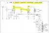
Robin - Lipman DC 1947.JPG
 
Last edited:
Ah. If I understand correctly, then, the resistor mod allows for fine-tuning the hum pot to the sweet spot, but in your case hasn't substantially lessoned the hum. Palustris stated earlier that an improperly connected hum pot can get noisier (worse) over time. It might be time to replace the pot as well, yeah? I think that's going to be my plan of action, as well as the resistor mod.

That stated, I'm curious what Palustris and Jeff think of Tadashi Asano's implementation of a hum pot with 30ohm 2W resistors on his revision to his father's 2A3 design. Should the resistor mod we've been discussing be applied here as well, or does Tadashi-san's use of resistors in the signal path from the 2A3 pins 1 and 4 negate the need of the mod?

EDIT: Jeff, I just reread that email with the note about the VT75 and the hum pots. You said the hum pots still need the 15-20ohm resistors soldered across them. Roger that.


Tadashi-Asano-2A3.png

Asano-2A3-humpot.png

Regarding the amp hum, the level might be slightly less after the resistor mod, but now the pot allows me to make it louder. Dowto1000, I am intrigued by your suggestion to try 6sl7 drivers. Garber shipped the X3 with 6sn7 tubes and I have many of these. Does the 6sl7 have the same current draw and operating voltage as the 6sn7 and can it be safely substituted for the latter? One of the many transformers on the X is probably for the filament. I have none of these tubes but could get a pair easily.
I also have not used this amp very much, only recently becoming interested in it after Don Garber’a passing.
 
Last edited:
Ah. If I understand correctly, then, the resistor mod allows for fine-tuning the hum pot to the sweet spot, but in your case hasn't substantially lessoned the hum. Palustris stated earlier that an improperly connected hum pot can get noisier (worse) over time. It might be time to replace the pot as well, yeah? I think that's going to be my plan of action, as well as the resistor mod.

That stated, I'm curious what Palustris and Jeff think of Tadashi Asano's implementation of a hum pot with 30ohm 2W resistors on his revision to his father's 2A3 design. Should the resistor mod we've been discussing be applied here as well, or does Tadashi-san's use of resistors in the signal path from the 2A3 pins 1 and 4 negate the need of the mod?


View attachment 1220074

View attachment 1220075


Hi GrantRay:

The suggested use of added 20 Ohm Rs across each end of the pot, to the center wiper has little, if anything, to do with the adjustability of hum. Actually, IMHO, in a good amp, a well designed one, there should be NO user adjustments what so ever ( IMHO, IME ).

In the case of Orest12, his improved hum adjustment was NOT the main goal of those two added Rs .....at all.

As stated by Palustris and I, a hum pot alone is a poor design, because the mechanical interface of the pot's adjustable wiper arm, to the pot's internal resistive element, which needs to be avoided. It acts as a diode-generator. ALL the 2A3's instantaneous peak current return to ground is running SOLELY through that wiper arm interface, a mechanical connection. The two added 20 Ohm 2 Watt high quality resistors, ( from each end of the hum pot, to wiper arm's center tab-connection ), transforms a " wiper-arm-only " path, to a DUAL signal path, consisting of the funky diode-like wiper arm AND paralleled and nicely-soldered 2 Watt resistors.

A soldered joint, in the cathode return of a 2A3 tube to ground, ( as one can imagine if thought about ), is MUCH better.

Orest12 heard it as increased dynamics and drive through the SE amp. Of course !! That is exactly what is has, with better internal transfer efficiency !!!

To answer your question about Tadashi Asano, adding Hum Pots to his Dad's, Isamu Asano 's amp design, here is what " I " think :

Again, this is ( IMHO, IME ) :

I say Tadashi made a BIG blunder !!! ( Isamu might now be rolling over in his grave. ) The son made the amp worse-sounding, poorer performing, on two key levels. Adding a wiper-arm in the 2A3 cathode's to-ground return path is a blunder, for the reasons as fully outlined above.

Adding those two 30 Ohm Rs is a second error IMHO.... equally serious. He made a 80 ohm about 6 Watt pot ( total value hum pot, 30+20+30 Ohms ) with 20 Ohms of fine - adjustment in the center. An E.E.'s dream approach. However, when Tadashi added those two 30 Ohm resistors, he also added extra solder joints and three Rs in series, which is added circuit complication. Resistors added in series, to get a value, should be AVOIDED in a good SE amp, due to unwanted solder joints. Resistors in parallel, on the other hand, if matched to each other to 0.01%, ( no skews) CAN be used very beneficially applied in a SE amp. See my Avatar .

I always find ( IMHO, IME ) that with un-needed parts added to a SE 2A3 DC amp, the worse the amp sounds !! KISS rules, when applied using a GOOD thoughtful implementation.

We did found above, that intelligent "R-doctoring" of a hum pot improves transfer efficiency in the Cathode's return-to-ground path. clearly audible, over time, to Orest12 ( and me, and I suspect, Palustris).

I would carefully and safely measure the 2A3's filament voltage, AT the tube socket, which is the point-of-use, and see how close it is to 2.5 VAC. Also measure the same 2A3 filament voltage across the 80 and 20 Ohm pot spans. YES, you really should add soldered Rs to ameliorate the wiper's sad mechanical-only diode-like interface. Optionally, you may want to add a single 100 Ohm pot, in place to the three-some.

Seek to "doctor" whatever pot is used there, be it across the stock 80 Ohm threesome, or across a new 100 Ohm pot, ends to the center / wiper's terminal.

Best sound, Grant Ray, will be what Isamu, the father did, NO pots, use the center tap and well wired ( leads ) of a 2.5 VCT filament transformer winding. Less is more !! Also, Tadashi added a return path for negative feedback, after the 3K 2A3 Rk, bias resistor, which ( negative feedback ) should be avoided like the plague in a SET amp !!

Back to modding the hum pot, the amp will sound better, because it will have much better transfer efficiency in the cathode return to ground.

Another possible alternative is to use a properly - rated Hammond Ef transformer, for each tube, below deck.

( IMHO, IME ) the best sounding 2A3 SE amp implementation, is to never ever use a hum pot, and rewire the Ef ( and power transformer ) lead outs, with higher quality lead out wire, ( I use Mil Spec wire with silver content, wide-band ). Seek to improve the amplifier's transfer efficiency in all possible ways. Its audible, and a good listener-builder just would think and act on it. An inch of bad wire can ruin the musical experience.

For now, ONLY carefully do 2A3's Ef VAC measurements, and report back to us !! Cool thread.

Ohh, by the way, the son Tadashi has " little clue " as to how to best lay out and, in particular, how to properly wire a SE amp ( IMHO, IME ) .

You NEVER EVER bundle wires as you have shown us in your second photo - with tie wraps, if you want best possible sound. The fields from each wire interact, one upon the other.

Do this : Cut off and discard ALL the that amp's tie wraps, and then, carefully position and float the wires three-dimensionally under the chassis, not touching the chassis if possible, nor touching each other. Wherever possible, if wire paths have to cross each other, try to do so at right angles. Wait till you hear that !!.

Finally, untwist, and float separately, the two Red-Red wires, from the power transformer to the tube rectifier socket, but only after you do the other wires. :)

Take PHOTOS, prior to snipping out the tie wraps, so you can simply return the amp to stock, should it be necessary in the future !! Have fun, LISTENING to that !! Please report back to us all, on the the four ( good quality ) Rs and separated wire runs.

Dowto1000

Son and DAD.JPG
 
Last edited:
Regarding the amp hum, the level might be slightly less after the resistor mod, but now the pot allows me to make it louder. Downtown 1000, I am intrigued
 
Sure, indeed, 6sn7 it is. From what little I know, this tube became popular in the 90’s; have 5 different amps/preamps using it—Cary, Audio Note, Fi, all bought about 98. No disrespect to the iconic Garber, the X amps were built to be cheap, and he admitted it. Have collected about 18 tube amps/preamps over the years; none hum except the Fi. The only other amp that even has a hum pot is a Dyna SCA35. As said, never worried about it; it’s just a fun discussion here. Best way to reduce hum—change speakers.
 
Those images aren't from my 2A3 amp, but I'll open it up and take a peek at the wiring job. Hopefully later today or tomorrow. On topic, new pot and resistors are ordered for the Fi X3 amp. Orest12, I totally agree on just using speakers that mate up well, but I also love learning by tinkering with small, very manageable repair jobs :)


Hi GrantRay:

The suggested use of added 20 Ohm Rs across each end of the pot, to the center wiper has little, if anything, to do with the adjustability of hum. In a good amp, a well designed one, there should be NO user adjustments what so ever ( IMHO, IME ).

In the case of Orest12, his improved hum adjustment was NOT the main goal of those two added Rs .....at all.

As stated by Palustris and I, a hum pot alone is a poor design, because the mechanical interface of the pot's adjustable wiper arm, to the pot's internal resistive element, which needs to be avoided. It acts as a diode-generator. ALL the 2A3's instantaneous peak current return to ground is running SOLELY through that wiper arm interface, a mechanical connection. The two added 20 Ohm 2 Watt high quality resistors, ( from each end of the hum pot, to wiper arm's center tab-connection ), transforms a " wiper-arm-only " path, to a DUAL signal path, consisting of the funky diode-like wiper arm AND paralleled and nicely-soldered 2 Watt resistors.

A soldered joint, in the cathode return of a 2A3 tube to ground, ( as one can imagine if thought about ), is MUCH better.

Orest12 heard it as increased dynamics and drive through the SE amp. Of course !! That is exactly what is has, with better internal transfer efficiency !!!

To answer your question about Tadashi Asano, adding Hum Pots to his Dad's, Isamu Asano 's amp design, here is what " I " think :

Again, this is ( IMHO, IME ) :

I say Tadashi made a BIG blunder !!! ( Isamu might now be rolling over in his grave. ) The son made the amp worse-sounding, poorer performing, on two key levels. Adding a wiper-arm in the 2A3 cathode's to-ground return path is a blunder, for the reasons as fully outlined above.

Adding those two 30 Ohm Rs is a second error IMHO.... equally serious. He made a 80 ohm about 6 Watt pot ( total value hum pot, 30+20+30 Ohms ) with 20 Ohms of fine - adjustment in the center. An E.E.'s dream approach. However, when Tadashi added those two 30 Ohm resistors, he also added three solder joints in series, which is added circuit complication. Resistors added in series, to get a value, should be AVOIDED in a good SE amp, due to unwanted solder joints. Resistors in parallel, on the other hand, if matched to each other to 0.01%, ( no skews) CAN be used very beneficially applied in a SE amp. See my Avatar .

I always find ( IMHO, IME ) that with un-needed parts added to a SE 2A3 DC amp, the worse it sounds !! KISS rules, when applied using a GOOD thoughtful implementation.

We did found above, that intelligent "R-doctoring" of a hum pot improves transfer efficiency in the Cathode's return-to-ground path. clearly audible, over time, to Orest12 ( and me, and I suspect, Palustris).

I would carefully and safely measure the 2A3's filament voltage, AT the tube socket, which is the point-of-use, and see how close it is to 2.5 VAC. Also measure the same 2A3 filament voltage across the 80 and 20 Ohm pot spans. YES, you really should add soldered Rs to ameliorate the wiper's sad mechanical-only diode-like interface. Optionally, you may want to add a single 100 Ohm pot, in place to the three-some.

Seek to "doctor" whatever pot is used there, be it across the stock 80 Ohm threesome, or across a new 100 Ohm pot, ends to the center / wiper's terminal.

Best sound, Grant Ray, will be what Isamu, the father did, NO pots, use the center tap and well wired ( leads ) of a 2.5 VCT filament transformer winding. Less is more !! Also, Tadashi added a return path for negative feedback, after the 3K 2A3 Rk, bias resistor, which ( negative feedback ) should be avoided like the plague in a SET amp !!

Back to modding the hum pot, the amp will sound better, because it will have much better transfer efficiency in the cathode return to ground.

Another possible alternative is to use a properly - rated Hammond Ef transformer, for each tube, below deck.

( IMHO, IME ) the best sounding 2A3 SE amp implementation, is to never ever use a hum pot, and rewire the Ef ( and power transformer ) lead outs, with higher quality lead out wire, ( I use Mil Spec wire with silver content, wide-band ) to improve the amplifier's transfer efficiency in all possible ways. Its audible, if a good listener-builder just would think and act on it. An inch of bad wire can ruin the musical experience.

For now, ONLY carefully do 2A3's Ef VAC measurements, and report back to us !! Cool thread.

Ohh, by the way, the son Tadashi has " little clue " as to how to best lay out and, in particular, how to properly wire a SE amp ( IMHO, IME ) .

You NEVER EVER bundle wires as you have shown us in your second photo - with tie wraps, if you want best possible sound. The fields from each wire interact, one upon the other.

Do this : Cut off and discard ALL the that amp's tie wraps, and then, carefully position and float the wires three-dimensionally under the chassis, not touching the chassis if possible, nor touching each other. Wherever possible, if wire paths have to cross each other, try to do so at right angles. Wait till you hear that !!.

Finally, untwist, and float separately, the two Red-Red wires, from the power transformer to the tube rectifier socket, but only after you do the other wires. :)

Take PHOTOS, prior to snipping out the tie wraps, so you can simply return the amp to stock, should it be necessary in the future !! Have fun, LISTENING to that !! Please report back to us all . Have fun listening to the four ( good quality ) Rs and separated wire runs.

Dowto1000

View attachment 1220254
 
Those images aren't from my 2A3 amp, but I'll open it up and take a peek at the wiring job. Hopefully later today or tomorrow. On topic, new pot and resistors are ordered for the Fi X3 amp. Orest12, I totally agree on just using speakers that mate up well, but I also love learning by tinkering with small, very manageable repair jobs :)


Well, I respect your two guys' comments, about using less sensitive speakers, but I don't agree. I use very well wired ALTEC VOTTs at home, A7-8s, and they are roughly about 100 dB one Watt, one meter. ( 515B and 802D , both horn loaded ).

The way an amp plays back music ..........is of prime importance to me.

I am more than willing to put up with hum, if the amp will play music as I like it to, which is uber-dynamic, tonally correct, and defined.

I always find that the quietest amps, are dead-sounding on music playback, due to the things that were added, to make it play silently .

We all have different listening priorities I know.

Dowto1000
 
Last edited:
Hi again, Grantray—like your idea of replacing the hum pot when doing the resistor adds; never thought of it; would probably been easier. Anyway, what would be the name and or specs of the pot you ordered that I might get one also.
Thanks much.
 
Hi again, Grantray—like your idea of replacing the hum pot when doing the resistor adds; never thought of it; would probably been easier. Anyway, what would be the name and or specs of the pot you ordered that I might get one also.
Thanks much.


His hum pot circuit is unique and different from yours. Likely NOT a direct order / install without checking yours first . He has an 80 Ohms total resistance, with only a 20 Ohm pot. ( 30+20+30 ) I would GUESS you might have a single100 Ohm Hum Pot. Measure yours, end to end. You must allow for the two Rs you added in parallel, to deduce what the pot R is in total. There are calculators on line for this...paralleled resistances. ALSO, measure the Ohms, from each end to the wiper / center tap, so you KNOW how much Ohmic offset you have selected by ear and use !! That would be good to know. If, for example, it was equal resistance on each side, you could eliminate the Hun Pot entirely IMHO, and do what I suggest, next paragraph :

WHY don't you access the filament transformer leads directly, fro,m the 2.5 VCT Ef XFR secondary, to the 2A3 tube socket, and simplify this circuit to the cathode with no hum pot.

If you have a 2.5 volt CENTER tapped transformer, use that center tap lead ( with improved wire ! ) to go to the Rk power resistor. I can send you high quality Military Spec lead wire, and take pictures of HOW to access the lead outs on the filament transformer.

What I suggest will be ( guessing - maybe ) 20 % better sonically than the additive of the two Rs you did. A new pot, if there is any difference at all, would likely be only 3 to 5% better maximum, as a WAG ( guess ).

Now a days, I never use hum pots, in SE DHT builds, and I always improve all the leads, on transformers and chokes, with Mil Spec quality wire. YMMV. I like what I do and hear. The Devil is in the Details. Fun.

Dowto1000
 
Hi again, Grantray—like your idea of replacing the hum pot when doing the resistor adds; never thought of it; would probably been easier. Anyway, what would be the name and or specs of the pot you ordered that I might get one also.
Thanks much.
I ordered a 100 ohm pot from Parts Express through their Amazon store. It's a hunch, really, as well as observations based on the shot you posted of the bottom of the pot in your amp as well as looking at the the pot in my X3. I'll take ohm measurements from Don's pot before I install the new one, just to make sure. If I'm right, then I'll drop in the new pot with the resistor mod. If I'm wrong, I'll at least now what the correct specs are for a replacement and only be out $10 :)
 
Thanks, gentlemen, just a little clarification—Grantray and I have X3, 300b output amps, quite different apparently from the smaller 2a3.
 
Thanks, gentlemen, just a little clarification—Grantray and I have X3, 300b output amps, quite different apparently from the smaller 2a3.


Hi.

Thanks for pointing this out. I was not familiar with all of Don's model offerings. Yours must be a three stage amp, with both halves of the dual triode 6SN7 performing different gain functions.

The HUM pot mod you did, applies to any DHT Finals tube, so you are good - to have it installed.

In the future, if feasible, try to go to a two stage DC amp, would be my general suggestion, as a result of all of my amplifier listening and A-Bing.

Why do I say this ?? Two stages, when direct coupled, properly executed, has outperformed any and all three stages amps I have ever compared them to. It is an addictive music presentation. Losing the third stage, allows the amp to become more transparent sounding, and with a mu of 100 driver, more direct, instantaneous with ZERO feedback, and less " electronic sounding ".

Two stages, well done, direct coupled, always easily has me the most involved and connected with the music, to my ear. My conclusion, the last dozen years, is that in tube audio, nothing can equal this KISS amplifier topology on High Efficiency speakers. .

Mind you, these are ONLY my own personal opinions. Please understand, I have been listening to tube amps and an original ALTEC 604 co-axial since early December 1944, when my Mom was nursing me at home. That 604 was Dad's ( and our family's ) mono speaker system.

Also, I have been hard " at it " DIY designing and building tube amps with help from two truly gifted mentors, since 1981 ( back then, it was a 2A3 P- P ). Of course, to adhere to our Forum's rules, and to acknowledge and be respectful to several recent admonishments, this is all entirely IMHO, and IME, and remember also this ....YMMV.

I bet Grant Ray will end up using his two stage DC Asano / JJ 2A3-40 amp, for most of his future serious listening. I will have to show him, besides the tie-wrap changes, how to improve the bypass capacitor, across the driver stage tube's cathode resistor next. A sensitive area of the design. For easily improved sound quality, it should never be any 100 uF 6.3 VDC electrolytic, as it is now. .That is ludicrous, IMHO, IME, ..... given today's superior industrial film caps. This Rk bypass modification will apply also to DC Fi amps, using the 6SF5 as a driver tube, but its costly to implement.

Dowto1000.
 
WOW, this thread keeps on growing. Without rehashing everything I would like to make a few points.

First a clarification about the pot/resistors: The two resistors are in parallel with the two legs of the pot. So with a 50r pot that I use and the 15r resistors that I use, the effective resistance between the cathode resistor and each leg of the (2A3 or 300B) filament is 9.38r. This provides for a very "narrow" window of adjustment. Now if you use a 20r resistor, the effective composite resistance is 11.11r; so in effect you are sending more current through the pot and less through the resistors, but "widening" the window of adjustment slightly. Again as Dowto1000 implies above, there should be little need for a wide window of adjustment. With a 20r pot and 30r resistors, the effective resistance is 10r and the adjustment window is very narrow, but now the majority of the current now goes through the pot not the resistors. So, as Dowto1000 has indicated above, this is a step backwards. .

As Dowto1000 and I have indicated above, these amps should really have an input sensitivity (1 Vrms) to allow the amp to be used without a preamp. This is not practical with the "X" amps since there is no place to put a volume control. I just don't understand why one of these "X" amps has a 6SN7 front end since it would require both two stages and RC coupling to drive the output tube to full output. The 6SF5/2A3 amp should have only two stages: input/driver and output. Personally, I have used the 6SF5 (and 6K5) as an input/driver tube and found it very good sounding.
 
Thanks Palustris,

Your post adds to the knowledge-base for readers. Very well written. Appreciate your contribution.

For newbies, there are on line calculators that compute parallel resistors, but you shed light on what does the most current and work.

I am guessing that these 300B "X" amps are three stages, and not totally DCed.

Loverly.

Dowto1000
 
Hi again, Grantray—like your idea of replacing the hum pot when doing the resistor adds; never thought of it; would probably been easier. Anyway, what would be the name and or specs of the pot you ordered that I might get one also.
Thanks much.

I've been busy getting the old C20 preamp's power supply rebuilt, but last night I finally got around to getting the X3 300B in a really happy place.

I did the resistor mod for the hum post, but before I did that, I made another discovery a week or so ago that significantly reduced hum: I swapped the Sovtek 5AR4 for a 1950's RCA 5V4G. The electrical differences between the 5AR4 and 5V4G are pretty minimal, (I built a spreadsheet for referencing rectifier specs) and I've also seen that Garber has opted for the 5V4G on occasion, such as the schematic you shared for the X-2A3. The drop in hum is significant. Not as low as my EIFL Asano 2A3 amp, but pretty dang close. The X3 now starts up, hums, goes quiet, hum picks up again, then quickly goes back down to a very acceptable level.

ON a side note, the amp is also really happy with vintage Raytheon 6Sn7GTBs for the drivers, the ones with the short black base plate and gold lettering on the bottle. I also tried new Tong-Sols that were rated low-noise, and they were anything but low. The hum was twice as loud with them!

So last night then I did the resistor mod:
For the the hum pot, I ended up keeping the original pot in place instead of replacing it. I studied Garber's assembly sequence, and quickly came to the conclusion that the requirements for a clean, properly executed replacement of the potentiometer would result in either major disassembly or skills of delicacy currently beyond me. No thanks. It's a shame, because the new pot feels and sounds way better when rotated. Another day, perhaps.

Anyway... As to resistors, I went with Audio Note 18R/2W Tantalums from the magnetic series. (Not the cheapest, but Parts Express is having a clearance sale on them, so I couldn't resist.) Between the resistor mod and the rectifier swap, all I can is that the amp is now a truly exceptional performer for the money. Hum is down another step, and the increased quality of output through the 846A Valencias, even at low volume, is audible, which I wasn't expecting. Although, that might because the general unhappiness of the amp was getting in the way.

Dowto1000 and Palastrius, thanks so much for the tip and all the subsequent info!
 
The Fi owners group in general, and the X3 in particular is limited, indeed. The pot-resistor mod is as far as I will ever go because of the unusual layout. I keep it as a curiosity piece, not used much. Enjoy your unit, hum and all.
 
The Fi owners group in general, and the X3 in particular is limited, indeed. The pot-resistor mod is as far as I will ever go because of the unusual layout. I keep it as a curiosity piece, not used much. Enjoy your unit, hum and all.

Between the RCA 5V4G and the pot-resistor mod, the hum is unnoticeable during playback and the amp performing like a champ. Now I just need to figure out if I can reconfigure those Hammond 125E output trannies for 16ohm to match the 846A Valencias :)
 
Fun to tinker with that old stuff. Once in a while I hook up a small system in the basement: old gear from Garber, George Wright, Van Alstein, Hafler; table and speakers from AR. It’s a hobby.
My X hum was never loud enough to be heard on playing; you have right now.
 
Glad to find this thread. I've been working to tame the hum of my X3 and have had some good successes. As I have them paired with RCA LC-1A's, hum is quite noticeble on the speakers. Between the addition of an isolation transformer between the wall and the amp, some better 6SN7's, and some good luck with some speaker wire (don't know how that makes a difference, but it does), the amplifier has calmed down noise wise and is sounding glorious.

I'll have to try the 5V4G in lieu of the 5AR4 I'm currently using. Hope you're still enjoying yours.
 
Glad to find this thread. I've been working to tame the hum of my X3 and have had some good successes. As I have them paired with RCA LC-1A's, hum is quite noticeble on the speakers. Between the addition of an isolation transformer between the wall and the amp, some better 6SN7's, and some good luck with some speaker wire (don't know how that makes a difference, but it does), the amplifier has calmed down noise wise and is sounding glorious.

I'll have to try the 5V4G in lieu of the 5AR4 I'm currently using. Hope you're still enjoying yours.

AFAIK, Don Garber used AC heating on the 300B filaments. That + the 3-stage 6SN7>300B circuit will produce audible hum on high efficiency speakers like the LC-1A. A 5VDC filament supply for each 300B will reduce hum if there's enough space in the X3 chassis.
 
Back
Top Bottom