• The move to the new server is done. There are some software and database maintenance updates in process. This has us passing the hat around to help out. We appreciate any donations. Seriously, even a dollar helps. The payment page may be found here - https://www.audiokarma.org/support.html

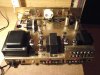
any idea what this is?

hrpuffnstuff

Active Member
Hi. I'm new to electronics so maybe this is a basic question. Does anyone know what the highlighted item is? After hearing a few cracks and pops from my speakers, seeing smoke, and smelling something burning last week, I took my the covers off my amp and noticed that 1 of the 2 of these were glowing red and had burn marks on it. There were two of these in the same area, and I removed the burnt one to see if I could find a replacement. Since I really don't know what it is or what the numbers and letters mean, I thought I would post a pic and see if anyone could help. If you know what it is, maybe you also know where I can get another one. Thanks for the help.
 

Attachments

  • help 1.jpg
    help 1.jpg
    112.4 KB · Views: 330
Register to hide this ad
Okay...I went to radio shack to find a replacement and couldn't find anything that looked like this one. Will a contemporary replacement look the same?
 
Damn! Wait!

Can you read the numbers on the burnt up one?
Are the numbers the same?

IF YOU CANNOT READ THE NUMBERS, STOP.

You need to use the right replacement.
Just because they LOOK the same, doesn't mean ANYTHING.

What is you amp? Maybe a service manual is available and we can find the correct part values.
 
Thanks for the replies. No, I can't read the numbers. It's a Hamlin's 20-20 (20 wpc) amp. I don't have a service manual, but I have a schematic that I don't know how to read.
 
Look on the schematic for any zigzag lines that have 4.7K or 4700 written next to them. It should also show the wattage rating. Watts are usually designated by just a W. This one will likely be 3 or more watts.
 
Just realized, the one shown is not the one he needs replaced. Best to just find a friend who can read the schematic and look at the amp.
 
If you replace the resistor, you are treating the symptom, not the root cause. Resistors don't usually undergo spontaneous combustion unless you have a short somewhere, tube failure or a lack of bias current etc.

Let us help you....give us some baic info on the amp and it's condition. Have you checked the tubes lately? Have you had any work done to it lately? If you just replace the resistor you might have the same thing happen again with a more catastrophic outcome.
 
scan and post the schematic

Dadbar is right. Those are high power resistors and don't usually go bad unless something else has happened to drastically (in your case) increase the current going through them. You need to check the circuit or have it checked for something else going wrong before putting it back in service.

Shelly_D
 
Dadbar is definitely right here. Resistors very very seldom fail on their own. When they cook, there is almost always something else at fault that caused it to burn up.
 
Yes, I would like to find the root cause. I am not a good judge of the condition, but i can post pictures. A few weeks ago I had a light hiss coming from the speakers. I wasn't sure if the hiss is normal for this type of amp, but it has a hum knob on the back of the amp. I turned to see how it effected the hiss and I started smelling something burning and the sound went dead. I looked at the amp and saw several burned wires. I took the amp to someone local, and he replaced the melted wires. He also tested the tubes. He also replaced one EL84 and the 5AR4 rectifier with a solid state replacement. I brought it home and hooked up a turntable, and it seemed to work okay except that when I turned the volume all the way down, there was still sound coming from the speakers. I began to plug in an mp3 player and tuner to see if the volume issue was consistent with the other components. When I plugged in the tuner, I heard several loud cracks and pops coming from the speakers and saw smoke and smelling something burning. I disconnected the amp, took off the covers, and plugged it back in. That is when I saw the resistor glowing red and its covering cracked and dull. So, I thought I would remove it and take it to radio shack to find a replacement. But I couldn't find anything that was similar there, and that is what prompted my post. Thank you everyone for the help!!
 

Attachments

  • pics122307001y.jpg
    pics122307001y.jpg
    131.7 KB · Views: 93
here are some more pictures...
 

Attachments

  • bottom1.jpg
    bottom1.jpg
    119.7 KB · Views: 45
  • bottom2.jpg
    bottom2.jpg
    117.8 KB · Views: 43
  • bottom3.jpg
    bottom3.jpg
    99.7 KB · Views: 34
  • top1.jpg
    top1.jpg
    90.9 KB · Views: 58
  • top2.jpg
    top2.jpg
    62.3 KB · Views: 40
I am assuming the thread got bumped becasue the issue has not been resolved.

It would appear the resistor R73 is your likely candidate for the burned out resistor, it would be an 8 Watt 300 Ohm resistor. If it is not R76 is the same value in the heater circuit of V1 and V2. If R73, it likely failed do to a shorted C48. Either that or the polarity is wrong on that capacitor, or it is inafvertantly shorted out. Judging by the images, the original caps should have had phenolic isolators. Which means the ground for the originals may not have been the chassis.

If ever in doubt, put a meter across the point where the Buss connects to one side of the power rectifier heater pin or common tie point of a SS full wave rectifier pair and install a 100K to 1 meg resistor from there to chassis ground, or the ground reference point when chassis is not the same as the B- buss. In your case since it has a solid state rectifier now, the plate current will flow instantly, and you only want to verify the rectifiers were installed correctly so you you will also know if your caps are correctly polarized for the circuit. In yours, the chassis is the negative, and the B voltage Buss is positive. All you nneed to do is power up the circuit for just a second or two to see what the meter shows for polairity. (if analog, the needle will drop below zero and slam against the meter stop.) If a digital multimeter is used, it will register as a "-" voltage if the rectifiers are in the circuit wrong.

Something that also looks not right is that is a singed mark near the socket of one of the output pairs, appears to be near pin 6 on one output tubes in one of the underchassis views- the larger of them shows it better Just the right of a vertical centerline and above center on a horizontal line. That may have contributed to the initial failure.

The schematic is a little small so resolution is not good. Your 47 Mfd caps under chassis also look to be 250 WVDC, the blur of the schematic indicates it should be 350Volts- which if the case, one of those 250's may be shorting.


Yes, I would like to find the root cause. I am not a good judge of the condition, but i can post pictures. A few weeks ago I had a light hiss coming from the speakers. I wasn't sure if the hiss is normal for this type of amp, but it has a hum knob on the back of the amp. I turned to see how it effected the hiss and I started smelling something burning and the sound went dead. I looked at the amp and saw several burned wires. I took the amp to someone local, and he replaced the melted wires. He also tested the tubes. He also replaced one EL84 and the 5AR4 rectifier with a solid state replacement. I brought it home and hooked up a turntable, and it seemed to work okay except that when I turned the volume all the way down, there was still sound coming from the speakers. I began to plug in an mp3 player and tuner to see if the volume issue was consistent with the other components. When I plugged in the tuner, I heard several loud cracks and pops coming from the speakers and saw smoke and smelling something burning. I disconnected the amp, took off the covers, and plugged it back in. That is when I saw the resistor glowing red and its covering cracked and dull. So, I thought I would remove it and take it to radio shack to find a replacement. But I couldn't find anything that was similar there, and that is what prompted my post. Thank you everyone for the help!!
 
Last edited:
I can't say I care for how those black caps are set up, just strapped down with exposed wiring like that. I would have gotten clamps and stood them up so the wiring is all under-chassis like the originals would have been. Just a personal opinion though. As long as the wiring to them is not shorted to ground, functionally its OK. Check closely where the wires come out of the chassis though. I do not see any chafe protection there so a wire could have rubbed through.

Something with those solid state replacements, they do not have any delay before kicking the high voltage on. What this means in a practical sense is the HV line is on before the tubes warm up and start to draw current, so the voltage will spike. If the caps are rated for this, its probably not a problem but its something to be aware of. There is a cap roughly dead center of the underside that looks like it might be bulged on top. Not sure if thats just the pic, but its worth a closer look. If they are in fact 250v caps where the schematic calls for a 350v, that would be a reasonable spot to look for the problem. It does look like the schematic calls out working voltages above 250v. Caps that aren't up to the voltage they are exposed to plus a much higher turn-on surge voltage would account for some problems.

R73 is the screen supply. If one of the output tubes self-destructed and shorted the screen, that resistor could well smoke. If one tube got replaced, that may have been what happened. I might be inclined to ask the guy who worked on it what was wrong with the tube he replaced. If it was in fact shorted, that might explain it. trouble is, if one shorted, it may have damaged one of the others, or one of the others could have had the same failure and the timing is just bad.
 
Whew...man you guys are awesome! Okay, I checked and R76 is indeed 8 watt 300ohm. So I will try to find a replacement. This amp ran fine for many months, so I don't think the polarity on the capacitor seems logical. I will take pictures of the uderchassis output tube sockets. Are output tubes the EL84's or another type? All of the blue caps say 33u 250v, including c48. Related to the SS rectifier, it was replaced because the guy who worked on it said the rectifier was shorting out causing fuses to blow. He replaced the EL34 tube because he said when he tested in in a tube tester, it would show good at first, and then slowing start to show bad as it heated up. Replacing the burnt wires and both tubes got the amp stable for a week until I was connecting the tuner and heard cracks and pops and saw and smelled the smoke.
 
The 250 volt types are too low, it appears in the schematic that they were 350 volt types. If you measure with a voltmeter, you only see the RMS equivalent, if you put it on a scope, the peak voltage will be higher, especially prior to the first filter cap.

I would suspect the filter caps at this point having failed if all are just 250 volt.

The EL84's are the finals.

It is easy to understand the SS replacements, some rectifier tubes are difficult to find even used.

When the power supply is sorted out, turn the amp on and watch the plates of the EL34's. If the plate (body inside the glass envelope you can see that is not supposed to glow) begins to glow red on one channel- shut it down. The same if more than one tube shows that. When that happens, there is a short in the final stage and the tube is pulling excess current. It sometimes takes a minute or two for it to develop, but it is possible there may be an output transformer shorting out. These can cause all manner of other issues if not caught soon enough (including hosue fire).

The SS rectifiers also raise the B voltage, so the safe thing to do when the other matters are sorted out, is to turn on the amp and monitor the plate to cathode voltages of the Finals first, then move back to phase inverters and drivers, and then the voltage amplifier/preamp stages to check to make sure Plate to Cathode voltage is not exceeded. The original rectifier had a plate resistance of about 2000 ohms, (and sufficient wattage) which is what you would need to install between the rectifiers and the first filter capacitor.
 
Back
Top Bottom