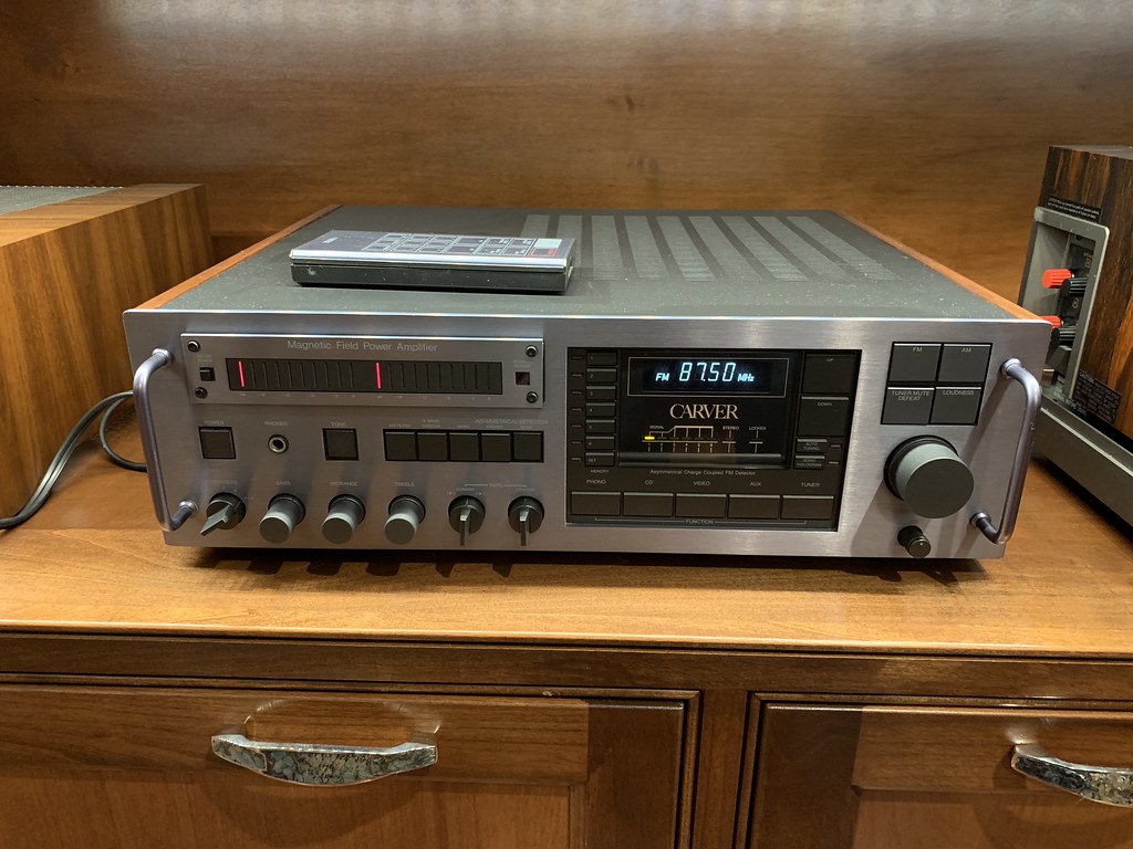
I found this posted elsewhere, it's great read.
SUNFIRE
SOME HISTORY
This amplifier had its beginning over fifteen years ago. After I sold Phase Linear, which I founded in the early 70's, and decided to start Carver Corporation, I wanted to come out with a new amplifier that would be light years ahead of anything currently available. I began work on a signal tracking power supply. Successfully implemented, an amplifier that incorporated such a power supply would be able to deliver lots of power, would run stone cold, would be incredibly efficient; all of the input power would become output power, it would be able to deliver massive amounts of current and would drive almost any impedance down to I ohm and below. It would have the potential of ultra reliability because it would be running cold, would not require heat sinks, and because it would be so efficient the power supply could be much smaller for the equivalent output power. (In a conventional amplifier only 20% to 30% of the input power actually appears at the output of the amplifier as usable audio power.) I toiled over a year trying to make this into a reality but couldn't get it to work. And so, after a year of working until two in the morning, I finally gave up and instead developed a different power supply called the Magnetic Field power supply. That power supply and its power amplifier became the original Carver "Cube." I used that to start Carver Corporation.
FAST FORWARD 13 YEARS
A little over two years ago, while still at Carver Corporation, I decided to have another go at it. I pulled out my notes from years ago, including the old patent; this time I succeeded, and succeeded in spades. The resulting amplifier was able to deliver massive power and humongous current, it could operate down to I ohm and it didn't get hot. In short, it fulfilled the original dreams I had years ago. I called that amplifier the Lightstar, and on December 17, 1992, I turned over the design to my engineering department for packaging (having completed about 95% of the work), and went on a sabbatical with the intention of final tweaking and voicing when I got back. Upon my return, I had a falling out with Carver Corporation and early last year left Carver to form Sunfire Corporation. At first it was Zeus Audio, named after my puppy, but I received a letter from an attorney who said, "No, you can't name it Zeus because we represent an amplifier company and we have names like Hercules, Aphrodite, Apollo, and Zeus." I renamed the company Silvermane, and promptly got a letter from another attorney who wrote, "No, I represent the Marvel Comics Group and we have a Superhero called Silvermane." Silvermane was out. Enter Sunfire.
SUNFIRE - HOW IT WORKS
In order to understand how the Sunfire amplifier works, it would be helpful to review a conventional amplifier and illustrate some of the very difficult engineering problems associated with powerful and very high current amplifiers. As you know, a conventional amplifier has a power supply, and for a 300 watt amplifier the power supply voltage is approximately 90 volts. That 90 volts is parked way up in the sky at 90 volts above ground zero. The audio signal varies under that voltage and as long as the amplitude of the audio signal remains below 90 volts, the amp will not clip or run out of power.
As an example, assume the output voltage at the loudspeaker is 30 volts, and10 amperes of current are flowing. The current starts at the power supply and flows through the transistors; as it goes through the transistors it makes them get hot. How hot? The measure of hotness is power; voltage becomes amperage. Remember, there are 10 amperes flowing and if there are 30 volts on the loudspeaker and there is a 90 volt power supply, that means there are 60 volts across the transistors. Again, the power is equal to volts times amps -- 60 volts times 10 amps equals 600 watts! That is not the power going to the load, that's the power going into the transistors as heat and must be gotten rid of. Hence, the transistors are mounted on a large heat sink; the heat is transferred to the heat sink and ultimately to the atmosphere.
Now, since the amplifier is only about 20% to 30% efficient, a lot more power has to go into the amplifier than comes out because 600 watts is going up in heat. Since it's inefficient, there must be lots of output transistors, lots of heat sink, and the power supply has to be much larger than would ordinarily be required in order to make up for all the power that's being wasted. Instead of a 30 pound power supply, it has to be 80 pounds. Well, so what? It's not difficult to add the power supply and heat sink necessary to allow the amplifier to deliver the power. However, a problem that is very insidious exists!
The problem is this. The output transistors that amplifier designers use are big 20 ampere output transistors. I use them, they are used in small amplifiers and large amplifiers. They are used in high end amplifiers and are even used in most of the big receivers these days. It's a standard part in our industry. It's the big Motorola, Toshiba the Sanyo or Sony equivalent. This transistor is rated at 20 amperes. However, it's only able to deliver 20 amperes if there are 10 volts or less across it. That's because it's a 200 watt part and can never dissipate more than 200 watts or its rating is exceeded.
At 50 volts for example, it can deliver only 4 amperes, because 4 times 50 is 200. At 90 volts it can deliver only 2.2 amperes. Going back to the earlier example with 60 volts across it, it can deliver only 3.3 amperes. Not very much current. If a designer wants to have an amplifier that's able to deliver lots of current into very low impedance loads, to deliver current in an unvarying way, no matter how difficult the loudspeaker impedance, no matter what the phase angle, he or she must use many paralleled output transistors -- lots and lots of them. Remember, they are not good for 20 amperes, they are really only good for a small portion of that, especially when driving low impedance loads.
Consequently, a designer has to parallel many, many output transistors. He or she must mount these transistors on huge heat sinks, and, because the amplifier is not very efficient it must have a huge power supply. Since each transistor draws its own idling current, the amplifier tends to run hot when it is just sitting there at idle. Biasing issues become very severe problems. To this day, solutions are still being sought. For example, Nelson Pass uses the sliding biasing circuit, and Krell uses a four-tiered switchable dynamic biasing circuit. Engineers and designers forever fret over whether they're going to bias their amplifiers Class A, or Class AB, or use a sliding bias scheme. Big problem. Still, amplifiers that can deliver these awesome and majestic currents do exist, but to get there you have to reach up to the big Mark Levinson's, Thresholds, the big Jeff Roland's, even the massive Krell's. Those amplifiers can deliver the performance, but they are very expensive -- starting at about $8,000. There is a better way.
THE TRACKING DOWNCONVERTER
In the Sunfire amplifier, that 90 volt power supply voltage that I mentioned earlier is removed from being parked 90 volts above ground, and is brought down and parked at only 6 volts above ground. The 90 volts no longer exists. Then, at any moment in time, regardless of what the output of the amplifier is, that power supply voltage will always be 6 volts above the output signal. If the output signal is zero, the output of the Tracking Downconverter will be 6 volts. If the output of the power amplifier is 30 volts, as in the previous example, the output of the Tracking Downconverter will be 36 volts. The voltage across the transistors remains a constant, unvarying 6 volts. Therein lies the beauty of the Tracking Downconverter.
Now, consider the previous example. The amplifier was delivering 30 volts to the load and10 amperes of current were flowing. That example resulted in 600 watts of power in the output transistors. In the Sunfire amplifier, that same 10 amperes is not dropping across 60 volts. Instead, it's dropping across 6 volts so the power is only 6 volts times 10 amps -- 60 watts wasted rather than 600 watts. Ten times less -- an order of magnitude less. It's so little power that the amplifier does not have a heat sink; it doesn't need one. There is not a heat sink to be seen in this amplifier, yet it can deliver well over 2,000 watts into 1 ohm. And because of its increased efficiency, the power supply doesn't have to weigh 80 pounds. The power supply can be a reasonable 30 pounds.
But here's the best part! Remember that a 20 ampere transistor can only deliver the full 20 amperes if there are 10 volts or less across it (because of its 200 watt limit). In the Sunfire, since there are only 6 volts across the transistors at all times, the full output current of 20 amperes can be delivered from each output transistor instead of 2, 3 or 4 amperes as in a conventional amplifier. Because each output transistor can deliver its full 20 amperes, the amp can deliver lots and lots of current into low impedance loads. In the Sunfire I used 12 output transistors per channel, each capable of 20 amperes; that represents a peak to peak output current of over 240 amperes. And it can do so into vanishing low load impedances. That's a staggering amount of current. That's what is required to have an amplifier with the performance of a $10,000 machine.
THE UNCANNY TRACKING DOWNCONVERTER AND A TRULY REMARKABLE FACT
A remarkable feature of the Tracking Downconverter is its intrinsic and unique ability to transform high voltage and low current to low voltage and high current. For example, if the input power to the downconverter is being delivered at a very high voltage, the output power can be delivered at a very high current. The transformation ratio; i.e., how much the current is increased, is in the same proportion that the voltage is decreased. In the case of the Sunfire, the power supply voltage is 2 times 125 volts, approximately 250 volts. Therefore, if the input current is 10 amperes and the output voltage is 25 volts; corresponding to a difficult or low load impedance; the output current will be 100 amperes because 250 divided by 25 is10. (The input current 10 amperes multiplied at the output by 10 for 100 amperes. A conventional amp could never do that, i.e. 10 amps in equals 10 amps out.) . It's this remarkable property of a Tracking Downconverter that allows the amplifier to deliver tons of current into vanishing low load impedances. It is also the property that allows the amp to run cold, to have a smaller power supply than would conventionally be required, and to possess a very flat output voltage characteristic. Whenever the load impedance is halved, the power just continuously doubles. A scientist would say "load invariant". Have you ever lusted for a $7,000 - $20,000 Mark Levinson, Roland, Krell, or Boulder amplifier?
At that point in the design, the Sunfire was an amplifier that could deliver almost limitless current, almost limitless voltage and deliver both simultaneously for tremendous output power, and runs cold. However, the design is not yet complete. The amplifier needs to be listened to. Listening to an amplifier in its design process is potentially the most time consuming, and is where the art of amplifier design enters the picture. When I listen, I first use a female vocalist and make certain that she can be accurately located in an acoustic space between the speakers and in such a way that a believable halo of space surrounds her, and she becomes palpably three dimensional. Also, I want her voice to be soft, musical, lyrical and have a great deal of believability. After the female voice, I listen to the male voice using baritones for the chestiness in the human male voice. When that part of the work is completed, I go to the symphony. I have in my head a template of what a symphony orchestra should sound like. I close my eyes and fit the sound of that symphony orchestra in my head, to the sound that my amplifier is making through the loudspeakers. In the case of the Sunfire, since human voice reproduction was so stunning, I found that the symphony orchestra locked in and I didn't have to do anything --- sort of like getting flesh tones correct on a color television receiver, all the other colors often lock in with very little effort. Getting the flesh tones correct is the most difficult process of designing a color set. But I digress. This effort was because I wanted a totally accurate amplifier.
CURRENT SOURCE - VOLTAGE SOURCE
At that point I had an amplifier that was tremendous -- lots of current, lots of voltage, incredible performance and then I added a unique feature: A choice of outputs -- voltage source output and current source output. Let me explain. A transistor is inherently a voltage source device; whenever an amplifier designer designs an amplifier with transistors, the result is a solid state amp that will typically have a very low output impedance approaching zero. A vacuum tube, on the other hand, is intrinsically a current source device. If an amplifier designer builds an amplifier out of vacuum tubes, he or she typically ends up with an amplifier that has a current source output characteristic, i.e., a higher output impedance. It's this high output impedance that is primarily responsible for at least 80% to 90% of what makes a vacuum tube amplifier sound like a vacuum tube amplifier -- a glow to the midrange, a soft high end, typically a layered stage depth and an open sound stage that is wider than it would be with a solid state amplifier. This musical presentation is very sumptuous and lovely to listen to, is quite captivating and the main reason many people love vacuum tube amplifiers.
Now, back to the Sunfire. Sunfire has two sets of output terminals on the back. One is a voltage source output with very low impedance. The other is a current source output with a higher impedance (current source) output characteristic. The choice of which to use is up to you. If you wish a solid state kind of sound, use the voltage source output terminals. If you want the vacuum tube sound, use the current source output terminals. Or, and this is the best part, you can bi-wire your speakers. Use the voltage source to the woofer, and wire the current source to the upper range of the system. That way you have the tight slam impact bass that a solid state amplifier can deliver, and you have the glow to the midrange, the sumptuous sound stage, and soft, delicately detailed highs that current source amplifiers typically deliver, i.e., vacuum tube amplifiers. The best of both worlds -- Again, when wired that way, you have tight bass, a beautiful sound stage, a sumptuous high end and a very believable sense of layered depth to the sound stage that is simply not available from a solid state amplifier. (At least from normal output impedance solid state amplifiers.)
SUNFIRE CIRCUIT DESCRIPTION, AMPLIFIER SECTION
The input stage is a low noise FET operational amplifier operated in a forced Class A single ended mode. The output of this stage drives balanced Class A level shifters and a balanced Class A voltage stage that swings the full rail of 250 volts peak to peak. The remainder of the current gain stages run full balanced with a constant VCE of 6 volts to the loudspeaker. It is heavily biased into the Class A region for small signals and Class AB region for large signals. Since the power dissipation in the output stages under simple quiescent bias conditions is 15 times less than a regular amplifier for the same output power, much more idle current can be used. The issue of how to bias this amplifier becomes moot -- all but irrelevant. All of the biasing issues simply evaporate because of the 6 volts. Even though it has a vacuum tube output characteristic on the current source output terminals, there is not a vacuum tube inside at all -- except for the meter pilot lamp, it's fully solid state.
THE UNCANNY TRACKING DOWNCONVERTER
Coming in from the outside world, we find a conventional main power supply; a large power transformer and filter capacitors. The output of this power supply feeds the Tracking Downconverter. The output of the Tracking Downconverter is fully regulated and tracks the audio, receiving its input signal from the same signal that drives the main amplifier. Essentially, the Tracking Downconverter is another power amplifier because its output voltage is in synchronism with, and tracks the audio signal, always above it a constant 6 volts. The input to the downconverter is a small signal Class A Motorola transistor. The output of this transistor drives a Texas Instrument PWM digital comparator. The output of the comparator drives a Hewlett Packard precision optocoupler which level shifts the digital control pulses to the gates of 12 International Rectifier Hexfets. The final output is smoothed into a continuously varying tracking voltage by the main energy storage downconverter inductor wound with humongous #12 wire on a low loss non-saturating ferrite inductor. The final energy storage capacitor is a 6.8 microfarad low ESR unit, and 12 dB of feedback is taken from this capacitor to the input stage. Finally, a Shotky free wheeling diode provides the energy return path for the Hexfet side of the downconverter inductor.