• The move to the new server is done. There are some software and database maintenance updates in process. This has us passing the hat around to help out. We appreciate any donations. Seriously, even a dollar helps. The payment page may be found here - https://www.audiokarma.org/support.html

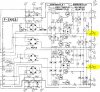
AU-717 F-2663 power supply board

john cronin

New Member
Hi my electronic knowledge is behind most on this site so I will try and get straight to the point. Ive just recapped a 717. It works but has excessive hum on inputs like Aux / Tuner when unconnected . When you short the input or attach a CD Player the hum goes away 100% but something is not right. My other similar AU-517 is dead quiet.

I am thinking the excessive hum with no input is due to issues on the 0V line Pins 21 / 22 on board F-2663

I read that board F-2723 (EQ Board) must be plugged in to see the correct output voltages + - 33V but with no real details why?

With board F-2663 unconnected to F-2723 I read +- 18V (wrong)
With board F-2663 unconnected to F-2723 I read 35V between OV Pin 21/22 and chassis ground (Bad ??)

Connecting both supply Molex plugs to F2723 makes no difference but if I also connect the audio out from F-2663 to F-2667 (Tap Play Board) the correct voltages appear.

So its picking up chassis ground from F-2667 and it connects back to Pin 21 / 22 on board F-2663 via F-2723 audio out.

I have a AU 517 so I compared results to the 717.
The 517 F-2675 showed the correct voltages with nothing connected. (wrong voltages on the 717)
The 5I7 F-2675 has no voltage potential to chassis ground (35V on the 717)
Both on the 517 and 717 power supply 0V connects to chassis ground back from F-2667 once audio out from F-2723 to F-2667 is connected (Same as the 717 so good)

So the only difference is this voltage potential. With F-2723 (EQ Board) unconnected to F-2663
I read 35V between Pins 21 or 22 to chassis GND on my Fluke meter .


I did reach out to leestereo on this and he told me its wrong and to check my work on F2723 but I can now confirm this is with F2723 out of the equation (not connected)

If someone is working on a 717 now please can you confirm if this is right. I am in London UK and all these 717's seem to be in the USA and Canada. They cost a fortune over here so buying another to be a donor is out the question for me.

On the 717 F-2263 board I change the capacitors to the same original spec and I changed some 10K resistors due to glue damage. I also changed ZD01-ZD02 – RD13E Zener to 1N5243B.

Big thanks in advance
John
 
Last edited:
Register to hide this ad
I'm in no way one of the experts here, but I went through one of these about 18 months ago. I remember there being a slight hum on the "phono" when nothing was plugged into it but nothing on the other inputs. I wrote it off to interference from all my bench gear as I had no other issues (other than a faulty volume pot.....you can probably find that thread on here). I'm trying to recall if there were any silkscreen vs. schematic issues but I can't remember. If you haven't done so, go back & look over your work & compare component orientation with silkscreen vs schematic.
 
Thanks PF Sound. I did take pics so components are in order etc. This is not my 1st restoration so maybe got a little too cocky in doing too much in one go. Ive always been able to scrape through and find problems in the past but this time I am stuck. The amp was non worker to start with but I should of done some pre checks. I was hoping putting all the screen covers back would resolve the issue. As mentioned earlier I compared issue to a 517 which is very similar and the only difference I could see was a voltage
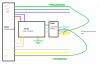
potential of 35V between pin 21or 22 to chassis ground on the 717. See below diagram.
 

Attachments

  • f2663a.JPG
    f2663a.JPG
    85.2 KB · Views: 36
There is a ground wire missing somewhere on input board, or tone board.
Thanks for replying. The tone control board F-2720 takes no ground from F-2663. Its gets it ground from the metal pots and switches connected to the metal chassis. I cannot see a dedicated ground wire to that board which I find strange. The 517 is the same.

F-2663 PSU Board takes in chassis ground on Pin 13 & 14
F-2723 EQ Board takes in chassis ground to the metal switch covers (only)
F-2723 EQ Board takes in chassis ground to Pin 35 from F-2667
 
Last edited:
Check the black ribbon cables that connect the Phono board (and input selector switch), to the rear panel sockets.
 
Next check the signal ground connections for cold solder or loose wire.
Thanks again. Please rule out dry joints. All connections have had old solder removed and leaded solder applied so better than reflow. I even removed each transistor and tested on my Atlas DCA55 etc and then scraped the legs to remove oxidation before re-installing etc.
Ive been caught out in the past by soldering onto old oxidised legs
 
Then you will have to trace it with a scope, where does it start with no sources connected....
 
W
Then you will have to trace it with a scope, where does it start with no sources connected....
Forget about Phono for now and just concentrate on Tuner or Aux. With nothing connected I get hum / buzz but if I connect a RCA short plug or an actual device like a tuner or cd player the noise goes completely goes.
 
W

Forget about Phono for now and just concentrate on Tuner or Aux. With nothing connected I get hum / buzz but if I connect a RCA short plug or an actual device like a tuner or cd player the noise goes completely goes.
I did not mean phono, I am aware tuner or aux are the problem, just a suggestion to use the scope, when it's happening, to find out where it originates. And what happens when it goes away by completing the missing connection through the other device ground (?) (CD player of whatever connected).
 
I did not mean phono, I am aware tuner or aux are the problem, just a suggestion to use the scope, when it's happening, to find out where it originates. And what happens when it goes away by completing the missing connection through the other device ground (?) (CD player of whatever connected).
Sorry I was not referring directly to you regarding phono. I have a scope so can do that and report back tomorrow. Many thanks for you time
 
The +/-33vdc feeds to the phono and tone board are the red/blue and yellow/gray wires visible at the top left and right of the power supply board and are referenced through the grounding plane across those two boards, when you have everything torn out of the unit testing for voltage you will get incorrect values. The method I used was to clip a mini-grabber to the ground pin on each side and THEN measure those wires for proper voltage.
With everything connected together including that ground point I mentioned above and all the amplifier leads and the two molex input connectors to the amp cards measure pins 20/22/24 to a chassis ground as well as pins 19/21/23, I use the turntable ground lug. You should see about 33 volts plus and minus on a DBT and closer to 35 volts on mains. If those are indeed correct we then move on to ground tracing. A quick test for example is from the outside ring of an input (say aux) to that turntable ground lug.
 
The +/-33vdc feeds to the phono and tone board are the red/blue and yellow/gray wires visible at the top left and right of the power supply board and are referenced through the grounding plane across those two boards, when you have everything torn out of the unit testing for voltage you will get incorrect values. The method I used was to clip a mini-grabber to the ground pin on each side and THEN measure those wires for proper voltage.
With everything connected together including that ground point I mentioned above and all the amplifier leads and the two molex input connectors to the amp cards measure pins 20/22/24 to a chassis ground as well as pins 19/21/23, I use the turntable ground lug. You should see about 33 volts plus and minus on a DBT and closer to 35 volts on mains. If those are indeed correct we then move on to ground tracing. A quick test for example is from the outside ring of an input (say aux) to that turntable ground lug.
 
Cheers Overundr1
With all boards connected up including signal path links I see correct voltage . With no boards connected I see the wrong voltage but if I force chassis ground onto Pins 21 and 22 with a mini grabber I then see the correct voltages on 17,19,23,25 and 18,20,24,26.

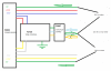
I just need to disconnect the Audio Out between F2723 and F2667 and that kills the GND to F2663 and the wrong voltages appear. Ive done a drawing (below) and green is the ground. Everywhere in Green is common through FE2723

Forcing chassis ground onto Pins 21 and 22 with a mini grabbing and taking F2723 and F2669 out of the equation I still get hum but its a lot quieter but not acceptable . Its in the audio path because it goes up and down with the volume. I think that's correct to say.

When I separate separate the pre-amp / power amp the noise completely goes.
Frequency of HUM is not power supply related like 50HZ or fully rectified 100Hz. The frequency changes with volume.

Could it be noisy transistors on the tone control board. Surely not both channels ?

I am not gonna let this beat me Help!!!!!!!!!!
 
Last edited:
Measuring the voltage potential difference between F2663 OV and Chassis GND (35V) I don't this on a 517
 

Attachments

  • 717 GROUNDB.png
    717 GROUNDB.png
    96.7 KB · Views: 9
Back
Top Bottom