


You are using an out of date browser. It may not display this or other websites correctly.
You should upgrade or use an alternative browser.
You should upgrade or use an alternative browser.
AU-717 F-2663 power supply board
- Thread starter john cronin
- Start date

Just an errant thought, if you reworked the phono/selector board and replaced the vd1212 diodes, one of them is very close to other components and if not careful will ground out causing mischief. Here is a board i was recently working on to compare to your work, this board working perfectly---

Might take a minute and check cap orientation as well as all the 2SC1400 transistors orientation if you replaced them with KSC1845's
Might take a minute and check cap orientation as well as all the 2SC1400 transistors orientation if you replaced them with KSC1845's
john cronin
New Member
That is correct. Does the hum disappear if you disconnect the phono/selector board F2667 from the tone board leaving everything else connected?
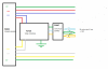
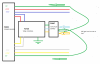
F2667 is a tiny board with just push switches. Its hard wired to the Tone Control Board. If I disconnect the power rails to F2723 and remove the audio link from F2667 I think that is the same thing. The hum is less but still not acceptable. I also have to force chassis ground back to F2663 so the Tone Control Board get the correct voltages from F2663 for this test. Exactly like the pic below
Attachments
john cronin
New Member
Just an errant thought, if you reworked the phono/selector board and replaced the vd1212 diodes, one of them is very close to other components and if not careful will ground out causing mischief. Here is a board i was recently working on to compare to your work, this board working perfectly---
View attachment 2756892
Might take a minute and check cap orientation as well as all the 2SC1400 transistors orientation if you replaced them with KSC1845's
I have inspected board F2723 again for components touching each other or interfering with ground etc and it looks good. Caps are correct orientation and I have changed NO transistors.
Aux and tuner paths do not really run through any electronics like the phono stage and because I still get hum without F2723 in play it leaves just two boards F2720 and F2663.
Attachments
Last edited:
john cronin
New Member
Seems a lot of the my previous updates are now irrelevant lol
Been playing around as you do. With the power rails removed from F2723 and the audio out from F2723 and then chassis ground force onto F2663 pins 21 / 22 applied and the hum goes 100% and note the audio input is open and not shorted but if I connect the audio out back to F2667 from F2723 the hum comes back on both channels. If I then put a RCA short plug on AUX then the hum goes.
I am 100% sure I can rule out all the other boards. The hum is coming from F2723 or maybe F2669 for sure.
LOL Ive gone round in circles but I an closing in on this fault. Overundr1 I am just gonna concentrate on F2723 / F2669 in much more detail. This is all good experience
Been playing around as you do. With the power rails removed from F2723 and the audio out from F2723 and then chassis ground force onto F2663 pins 21 / 22 applied and the hum goes 100% and note the audio input is open and not shorted but if I connect the audio out back to F2667 from F2723 the hum comes back on both channels. If I then put a RCA short plug on AUX then the hum goes.
I am 100% sure I can rule out all the other boards. The hum is coming from F2723 or maybe F2669 for sure.
LOL Ive gone round in circles but I an closing in on this fault. Overundr1 I am just gonna concentrate on F2723 / F2669 in much more detail. This is all good experience
Last edited:
john cronin
New Member
I am closing in on this fault lol but sometimes you have to walk away and do something else before you see the light of success.
TBC
TBC
john cronin
New Member
I have also have a 517 that needs to be restored so I removed F-2723 and restored the board to the same standard. I then installed the board in the 717 and its perfect. No hum on Aux / Tuner etc.
So I know its a problem just on F-2723 now. Something is interfering with the signal ground plane affecting Aux and Tuner on the other board.
Soldering is clean and tidy. Nothing looks out of place.
OK another baby step closer but WTF is wrong ?
I will try this below next.
For Tuner / Aux board F2723 requires no power so I will cut power to the F2723 board but leave the signal path in place and see if hum goes.
I will force chassis ground to F-2663 pin 21/22 so the tone control board is powered by the correct voltages
I will update
So I know its a problem just on F-2723 now. Something is interfering with the signal ground plane affecting Aux and Tuner on the other board.
Soldering is clean and tidy. Nothing looks out of place.
OK another baby step closer but WTF is wrong ?
I will try this below next.
For Tuner / Aux board F2723 requires no power so I will cut power to the F2723 board but leave the signal path in place and see if hum goes.
I will force chassis ground to F-2663 pin 21/22 so the tone control board is powered by the correct voltages
I will update
john cronin
New Member
Faulty new cap perhaps?
May have to pull and check each one
Did you change any transistors?
Brand new ELNA / Nichicon capacitors being bad ? Ive ruled that out because they are new but you are right I need to review and check everyone. I have not changed any transistors they are all still the original.
All I have changed on this board is as follows
1. All the electrolytic capacitors (original uF values)
2. Most ceramic capacitors (original values uF values)
4. D01-4 1N4148 in series
5. R47,48,49.50 82r (old ones were well out of tolerance and looked really ill )
Didn't need to change the ceramics. Don't know really why I did. The new ones are blue and look more cool lol.


Did this board have the F-2669 (input sockets) board attached when you fitted it in the AU-717 ?I have also have a 517 that needs to be restored so I removed F-2723 and restored the board to the same standard.
If so...
Pin 11 & pin 12 on ribbon cables ok?
C601 ok?
Last edited:
john cronin
New Member
Guys many thanks for your support especially Overundr1 who showed a lot of interest and stayed with me. Ive fixed the issue.
The suspect faulty F2723 board was humming from the LED sector power source. When you install an LED on selected source the Hum goes. One to look out for ?
My wasted time is someone's saved time
https://www.youtube.com/shorts/4Ej42XCdhV4
The suspect faulty F2723 board was humming from the LED sector power source. When you install an LED on selected source the Hum goes. One to look out for ?
My wasted time is someone's saved time
https://www.youtube.com/shorts/4Ej42XCdhV4


That’s what it looks like in the video!So if I understand correctly all this because LED's were unplugged?

CrSens
Super Member
Madness!That’s what it looks like in the video!

I am very pleased you found this one, well done. But I am stunned at the cause! - that really is a strange one.The suspect faulty F2723 board was humming from the LED sector power source. When you install an LED on selected source the Hum goes. One to look out for ?
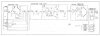
There is a black wire that connects the two switches together marked (A) on the schematic. You can see on the picture I posted of that board where the wire starts top right next to the 3 in the board label and travels over to the back of the other select switch. I would suggest checking that wire as it may be the ground wire for those two selector switches. I have never seen a 517/717 act like that and have done a bunch of them over the years.
john cronin
New Member
There is a black wire that connects the two switches together marked (A) on the schematic. You can see on the picture I posted of that board where the wire starts top right next to the 3 in the board label and travels over to the back of the other select switch. I would suggest checking that wire as it may be the ground wire for those two selector switches. I have never seen a 517/717 act like that and have done a bunch of them over the years.