

You are using an out of date browser. It may not display this or other websites correctly.
You should upgrade or use an alternative browser.
You should upgrade or use an alternative browser.

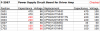

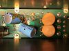

No double sided boards in the 9900. I believe the AU-20000 has them, though.I haven’t been inside an AU-9900 but if it has the double sided PCBs I’d recommend soldering a wire through the pass throughs.
The plated holes tend to deteriorate over time.

TupolevFan
Super Member
My choice for Semiconductors would be the following for F2568:
TR02 - MJE15031G or even better MJE15033G
TR01 - MJE15030G or even better MJE15032G
TR04 - KSA1013YTA or (if you do not mind twisting pins) better ZTX796A (Pinout is EBC !!!)
TR03 - KCS2383YTA or (if you do not mind twisting pins) better ZTX696B (Pinout is EBC !!!)
TR06 - can use KSA992FB or (if you do not mind twisting pins) better ZTX796A (Pinout is EBC !!!)
TR05 - can use KSC1845F or (if you do not mind twisting pins) better ZTX696B (Pinout is EBC !!!)
ZD03 - Vishay BZX55B10-TR 2% zener.
If i understand correctly then ZD01 and ZD02 are 39V 0.5W zeners then use Vishay BZX55B39-TAP 2%.
Now regarding C15 which shunts ZD03 I would use here Hybrid polymer capacitor. As Zenner itself has very low internal resistance I would use here if space permits United Chemi-Con part# HHSE630ELL101MJC5S
as those have very low ESR.
Normally I would say bump up C03 and C04 to 220uF or even 270uF to improve rejection rate however here is ZD01 and ZD02 solving it and in reality the regulator would venture very well even without those caps or should i say loss of capacitance here would not be critical when zener is in place, for the sake of smoothening and shunting and filtering noise I would again use same United Chemi-Con part# HHSE630ELL101MJC5S in place of C04 and C03.
C02, C01 I would bump up to 680 X 80 V or even to 820 X 80 if space permits.
C12,C11 I would bump up to 220 x 63V
Just my 2 cents.
EDIT I made a mistake. I somehow thought that ZD03 is 13V zener.
ZD03 should be BZX55B10-TR
TR02 - MJE15031G or even better MJE15033G
TR01 - MJE15030G or even better MJE15032G
TR04 - KSA1013YTA or (if you do not mind twisting pins) better ZTX796A (Pinout is EBC !!!)
TR03 - KCS2383YTA or (if you do not mind twisting pins) better ZTX696B (Pinout is EBC !!!)
TR06 - can use KSA992FB or (if you do not mind twisting pins) better ZTX796A (Pinout is EBC !!!)
TR05 - can use KSC1845F or (if you do not mind twisting pins) better ZTX696B (Pinout is EBC !!!)
ZD03 - Vishay BZX55B10-TR 2% zener.
If i understand correctly then ZD01 and ZD02 are 39V 0.5W zeners then use Vishay BZX55B39-TAP 2%.
Now regarding C15 which shunts ZD03 I would use here Hybrid polymer capacitor. As Zenner itself has very low internal resistance I would use here if space permits United Chemi-Con part# HHSE630ELL101MJC5S
as those have very low ESR.
Normally I would say bump up C03 and C04 to 220uF or even 270uF to improve rejection rate however here is ZD01 and ZD02 solving it and in reality the regulator would venture very well even without those caps or should i say loss of capacitance here would not be critical when zener is in place, for the sake of smoothening and shunting and filtering noise I would again use same United Chemi-Con part# HHSE630ELL101MJC5S in place of C04 and C03.
C02, C01 I would bump up to 680 X 80 V or even to 820 X 80 if space permits.
C12,C11 I would bump up to 220 x 63V
Just my 2 cents.
EDIT I made a mistake. I somehow thought that ZD03 is 13V zener.
ZD03 should be BZX55B10-TR
Last edited:
Ran into some questions on the F-2570 equalizer board. C9-12 are listed as e-caps in the SM, but don't look like e-caps to me. What kind of capacitors are these and do they need replacing? C9,10 have "IH 102F" printed on them with some kind of logo, SM lists them as 1 µF 50V. C11,12 have "IH 472F" printed on them, SM lists them as 4.7 µF 50 V. Do the markings match the listed values?

C25, 26 appear to be on the foil side of the board and are marked "IH 270J", SM lists them as 0.47 µF 50V. Again wondering if this is accurate and if these need replacing?
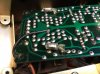
C25, 26 appear to be on the foil side of the board and are marked "IH 270J", SM lists them as 0.47 µF 50V. Again wondering if this is accurate and if these need replacing?
My choice for Semiconductors would be the following for F2568:
TR02 - MJE15031G or even better MJE15033G
TR01 - MJE15030G or even better MJE15032G
TR04 - KSA1013YTA or (if you do not mind twisting pins) better ZTX796A (Pinout is EBC !!!)
TR03 - KCS2383YTA or (if you do not mind twisting pins) better ZTX696B (Pinout is EBC !!!)
TR06 - can use KSA992FB or (if you do not mind twisting pins) better ZTX796A (Pinout is EBC !!!)
TR05 - can use KSC1845F or (if you do not mind twisting pins) better ZTX696B (Pinout is EBC !!!)
ZD03 - Vishay BZX55B10-TR 2% zener.
If i understand correctly then ZD01 and ZD02 are 39V 0.5W zeners then use Vishay BZX55B39-TAP 2%.
Now regarding C15 which shunts ZD03 I would use here Hybrid polymer capacitor. As Zenner itself has very low internal resistance I would use here if space permits United Chemi-Con part# HHSE630ELL101MJC5S
as those have very low ESR.
Normally I would say bump up C03 and C04 to 220uF or even 270uF to improve rejection rate however here is ZD01 and ZD02 solving it and in reality the regulator would venture very well even without those caps or should i say loss of capacitance here would not be critical when zener is in place, for the sake of smoothening and shunting and filtering noise I would again use same United Chemi-Con part# HHSE630ELL101MJC5S in place of C04 and C03.
C02, C01 I would bump up to 680 X 80 V or even to 820 X 80 if space permits.
C12,C11 I would bump up to 220 x 63V
Just my 2 cents.
EDIT I made a mistake. I somehow thought that ZD03 is 13V zener.
ZD03 should be BZX55B10-TR
Thanks for the suggestions, though not looking to replace everything, only parts that are known to be problematic, which is what I listed on my BOM for F-2568. 2SA726 are known to be bad transistors, and I have found the same in the receivers I've had, so makes sense to replace them. Standard recommendation for replacement is KSA992. Just wondering why you recommend something different for TR04? Standard replacement for 2SC1313 is KSC1845, why something different for TR03?
TupolevFan
Super Member
Well that is true that KSC1845F can in many cases replace 2SC1313. However it is not really always 1 to 1 replacement. Here it is part of the darlington transistor and I should say in this particular case 1845F will be OK in terms of collector currents and power dissipation. But I would feel more confident (in terms of collector current and max power dissipation) with ZTX696 or KSC2383Y also with later the rejection rate might slightly drop because hfe of 1313 is almost twice higher. for TR06 and TR05 (error sensing transistors which drive Darlington transistor TR01,TR03 and TR02,TR04) KSA992/KSC1845 are OK as those collector currents will be at the bay no matter what, but again me personally would use here ZTX.Thanks for the suggestions, though not looking to replace everything, only parts that are known to be problematic, which is what I listed on my BOM for F-2568. 2SA726 are known to be bad transistors, and I have found the same in the receivers I've had, so makes sense to replace them. Standard recommendation for replacement is KSA992. Just wondering why you recommend something different for TR04? Standard replacement for 2SC1313 is KSC1845, why something different for TR03?
Yes MJE150xx are overkill for this task but I would say "hot" overkill. and yes KSA1013Y/KSC2383Y ( do not use "O" version as hfe even lower) or ZTX796/ZTX696 overkill as well but again in a good way. In the end remember it is the Power supply of your amp and it should be bullet proof. That is just how i see it.
Well that is true that KSC1845F can in many cases replace 2SC1313. However it is not really always 1 to 1 replacement. Here it is part of the darlington transistor and I should say in this particular case 1845F will be OK in terms of collector currents and power dissipation. But I would feel more confident (in terms of collector current and max power dissipation) with ZTX696 or KSC2383Y also with later the rejection rate might slightly drop because hfe of 1313 is almost twice higher. for TR06 and TR05 (error sensing transistors which drive Darlington transistor TR01,TR03 and TR02,TR04) KSA992/KSC1845 are OK as those collector currents will be at the bay no matter what, but again me personally would use here ZTX.
Yes MJE150xx are overkill for this task but I would say "hot" overkill. and yes KSA1013Y/KSC2383Y ( do not use "O" version as hfe even lower) or ZTX796/ZTX696 overkill as well but again in a good way. In the end remember it is the Power supply of your amp and it should be bullet proof. That is just how i see it.
Great! Thanks for the explanation, that helps me understand the circuit and their purpose better. I've got KSA1013YTA, KSC2383YTA, MJE15032G, and MJ15033G on hand, so I will make those subs on the list.

Regarding those capacitors - you are forgetting the recapping mantra.....
Replace parts so they are the same as what you find in your unit - the unit worked once and probably left the factory like that. The schematic and the parts lists could be anything, and never had to function as a working unit.

Replace parts so they are the same as what you find in your unit - the unit worked once and probably left the factory like that. The schematic and the parts lists could be anything, and never had to function as a working unit.
Oh, yes, you are exactly right, and the amp is currently working and has not had issues as long as I have owned it. However, it's easiest for me to start with the SM for a list of components, then check the unit and make corrections based on what is in there. If I start with the schematic, I fear I will miss something. In either case, need to replace what is actually in there, as you say. Totally agree. That's why I'm taking the time with this unit to check every board against the SM list. Some boards are matching 100% with SM, others it's clear the SM is in error. So, I think I'm following your directive...Regarding those capacitors - you are forgetting the recapping mantra.....
Replace parts so they are the same as what you find in your unit - the unit worked once and probably left the factory like that. The schematic and the parts lists could be anything, and never had to function as a working unit.


Ignore the SM. Ignore the schematic. Use the unit for a parts list.
Leave films.
Leave films.
Finished checking all of the boards and confirming components in each position for capacitors. Here are the lists for each board with replacements indicated. Did not see any caps that were obviously "low leakage", but I'm not familiar with all of the different lines of capacitors from that era. Please let me know if there are any mistakes in the replacements I have chosen or if a UPW replacement should be a UKL or some other series of cap. I also did not select a replacement for the filter caps, as it was not obvious what would be best or fit in the position. Any suggestions would be appreciated, or if it might be ok to leave the originals in. I know some techs don't touch the filter caps because the leakage on them over time is very low.
Replacement parts in blue are what I have on hand. The rest I will need to order. Capacitor values in red are discrepancies from SM.
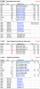
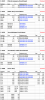
Replacement parts in blue are what I have on hand. The rest I will need to order. Capacitor values in red are discrepancies from SM.
I don't think there's any low leakage caps here, they used a lot of films and bipolars.
As far as main filters, you can get creative. I use Nichicon VR's and just solder the leads onto the busbars. Cheap and works well, but doesn't look good. Screw type caps can be modified to work, but takes a lot more time and much more money.
However, they should be replaced. No reason to half-ass it, this unit deserves the full treatment.
As far as main filters, you can get creative. I use Nichicon VR's and just solder the leads onto the busbars. Cheap and works well, but doesn't look good. Screw type caps can be modified to work, but takes a lot more time and much more money.
However, they should be replaced. No reason to half-ass it, this unit deserves the full treatment.
TupolevFan
Super Member
For the phono corrector board (F2570). Did you actually measure that Wima 10uF would fit ? if not look at my previous posts ( in reality you need just 2). Also C09, C10,C11,C12 are
not e-caps those are film and values you listed are in nF (nano) and on schematics they are in fact specified in pF (pico)
not e-caps those are film and values you listed are in nF (nano) and on schematics they are in fact specified in pF (pico)
I will check the 10 µF films. I’ve used them before in the Eight and did not have a problem with space.
Any thoughts on C25/26? I’ve not seen caps that look like that before, so am not familiar with what type they are.
Will take a look at options for the filter caps. There are a couple of threads on filter caps for the 9900.
Any thoughts on C25/26? I’ve not seen caps that look like that before, so am not familiar with what type they are.
Will take a look at options for the filter caps. There are a couple of threads on filter caps for the 9900.
TupolevFan
Super Member
I will check the 10 µF films. I’ve used them before in the Eight and did not have a problem with space.
Any thoughts on C25/26? I’ve not seen caps that look like that before, so am not familiar with what type they are.
Will take a look at options for the filter caps. There are a couple of threads on filter caps for the 9900.
Hmm I do not see C25/26 on F2570. Are we talking about different board? I see C01 C02 is 0.47uF which probably could be upgraded to polypropylene (need to see size)
Now that you say that, I meant C23/24, which are shown in the second picture in post #25. I assume those are not electrolytics. I'm just not familiar with them.Hmm I do not see C25/26 on F2570. Are we talking about different board? I see C01 C02 is 0.47uF which probably could be upgraded to polypropylene (need to see size)
I don't see C25/26 on the schematic, so must be another SM error.
TupolevFan
Super Member
Those (C25/C26) definitely are not e-caps. So leave them alone.
Just enter the type number into the AK 'search' box - I just tried this and got 96 hits where people have encountered 2SC1364 and done something about it.What would be the recommended replacement here?