• The move to the new server is done. There are some software and database maintenance updates in process. This has us passing the hat around to help out. We appreciate any donations. Seriously, even a dollar helps. The payment page may be found here - https://www.audiokarma.org/support.html

AU-999 initial powerup, after restoration

bolero

Super Member
What is the best procedure to power up an AU-999 after a full rebuild?

I've got a pair of 8ohm 100w resistors wired up on a board, and a dim bulb plug ready to go.

New 1k & 5k trimmers are set to mid range: after reading thru the forum these are the steps I think I need to take:

1. Run the dim bulb in line with the power cord, and turn the amp on with no speaker load ( and not on the headphone setting ). If the bulb dims after initial load:

2. Proceed to set amp bias to 50% ( half of 13mA, so 6-7 mA ) with probes hooked on either end of resistors R853, R854 on boards 1231 & 1277 underneath the chassis.

3. Turn off amp, remove dim bulb, plug amp into wall voltage

4. Let amp warm up & stabilize for 20 mins or so, then set bias to 100% ( 13mA ) with probes on either end of resistors R853, R854 on boards 1231 & 1277 underneath the chassis.

5. Set balance trimmers, monitoring with probes in speaker outputs.

6. Monitor amp & let it idle for a while

7. Power off, hook up dim bulb again & 100w 8ohm resistors into speaker outs. Power back up, turn the volume up a bit with no signal input & make sure the DBT test passes.

8. Hook speakers up & test a real audio source.

Am I missing anything?

-->with the new 12,000uF filter caps, I installed a beefier rectifier too ( based on Stereofun's 999 thread). The rectifier's metal base plate is grounded to the chassis, is that ok? or does it need a non-conductive spacer?

And is it best to run new filter caps for any length of time, to make sure they charge fully? I heard they have a memory, so if you don't let them charge fully they won't reach full potential? Or am I getting confused with batteries?

Thanks!

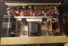
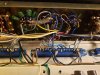
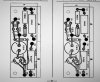
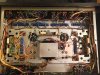
Here are a couple pics, along with the 1231/1277 board diagram
 

Attachments
  • 999_bottom.jpg
    999_bottom.jpg
    162.9 KB · Views: 76
  • 999_top.jpg
    999_top.jpg
    115 KB · Views: 74
  • 999_bass_EQ.jpg
    999_bass_EQ.jpg
    118.8 KB · Views: 72
  • 999_1231_1277.jpg
    999_1231_1277.jpg
    117.2 KB · Views: 63
Last edited:
Register to hide this ad
The rectifier's metal base plate is grounded to the chassis, is that ok? or does it need a non-conductive spacer?
just for heat dissipation, that looks like 30/35A full bridge, so heat will never should be an issue.
I heard they have a memory, so if you don't let them charge fully they won't reach full potential? Or am I getting confused with batteries?
mmmm lithium capacitors! just kidding.

Good work!
 
Thanks guys!

gslikker I will read that thread. I still have some cosmetic fixes & cleaning to do on the amp, but wanted to tackle the hard work first.

I didn't think it would take this long! But making parts lists, ordering the wrong parts, then reordering the right parts :) , and general research is very time consuming.
 
There's a typo up there in my initial post, it should be milliVolts, not milliAmps:

"2. Proceed to set amp bias to 50% ( half of 13mV, so 6-7 mV ) with probes hooked on either end of resistors R853, R854 on boards 1231 & 1277 underneath the chassis."
 
Allright, I powered it up on the DBT, which flashed for a second & then went out. Lights on the 999 were working, so it's getting power ( I had it on "aux" input, Speaker A, but volume at 0 and no signal input, or speaker load )

However I am not getting *any* DC voltage across either emitter resistor 853/854. And adjusting VR803 doesn't have any effect.

Which means the driver boards must not be getting any voltage?

If I'd blown the output transistors, would there be voltage across 853/854?

Thanks!

*edit: I guess I can check R845 to see if there's any current across it
 
Last edited:
Allright, I powered it up on the DBT, which flashed for a second & then went out. Lights on the 999 were working, so it's getting power ( I had it on "aux" input, Speaker A, but volume at 0 and no signal input, or speaker load )

However I am not getting *any* DC voltage across either emitter resistor 853/854. And adjusting VR803 doesn't have any effect.

Which means the driver boards must not be getting any voltage?

If I'd blown the output transistors, would there be voltage across 853/854?

Thanks!

*edit: I guess I can check R845 to see if there's any current across it
Keep turning the trimmer, it will turn quite some way before the bias current wakes up...
 
Ah! Ok well I found some more data:

R845 on both driver boards has voltage across it, ranging from 9-13V as I adjust VR803

Then I hooked my other multimeter up to the 853 & 854 resistors, managed to get 6.3mV out of one, and 3mV out of the other. But only at the extreme end of trimmer VR803. Like it's running out of range.

I wonder if I screwed up the 1K & 5K trimmer installs. They are single turn fwiw.
 
What I'll do is dial back the trimmers, take it off the DBT, and see if I get more range out of them.

After I double check that I installed them where they are supposed to be! :)
 
Still on the DBT: I got one to go up to 12mV, but only at the very end of adj range.....I wonder if these trimmers have some kind of taper on them? I assumed they would be linear, never thought to check.

Ps thanks for the advice! Am investigating
 
Confirmed: 1K trimmers installed at VR803

Took it off the DBT, will let it idle for a while before I try anything else. There's no harm in running with the bias at 0mV?

Strange: the right driver bias adj seems to affect both channels though.
 
Yeah something is up with the bias circuit/trimmers. Both maxxed out only give me 3mV or so each. But if I turn one down, the other goes up to 7 or 8mV. It's like both channels combined are sharing a maximum of 8mV.
 
DC offset adjusted to less than 5mV per channel at the speaker outs.

I must have a short somewhere, or maybe a bad transistor. I only changed out the transistors on the driver boards for ZTX's. There were no flying saucers in this amp.

Going to sleep on it & examine the schematic tommorrow. Zzzz....
 
Looking at the schematic I was trying to see where the two VR803's might have a connection that shouldn't be, as they seem to be sharing a current source & are inversely affecting each other, monitoring bias at R853 & R854 resistors. ( this shouldn't be happening, right? L/R bias should be independantly adjustable? )

With the amp off, I measured a stereo to 2x mono cable at the headphone out: L/R had 17-22 K ohm resistance between each channel, is this normal? I thought L/R channels would be separate?

Grounds L/R had 0 ohms between them

L & R to ground were 650-800 K ohms each.

Any clues in there?

Thanks!
 
Last edited:
Thanks!

I can only get a bias reading if VR803 is cranked all the way, and both channels are inversely affecting one another.

I can get max 4mV on both LR, but if I turn one down to 0 the other goes up to 8-10mV.

So I assume there is a short somewhere, they should be independant?
 
Back
Top Bottom