

You are using an out of date browser. It may not display this or other websites correctly.
You should upgrade or use an alternative browser.
You should upgrade or use an alternative browser.

bolero
Super Member
Here are the filter caps I used
https://www.digikey.com/en/products...CiACAzADjSgzgUwCcBLPHdTAWjAAYAWWigOQRRAF0BfIA
https://www.digikey.com/en/products...CiACAzADjSgzgUwCcBLPHdTAWjAAYAWWigOQRRAF0BfIA
bolero
Super Member
Well allright!!
That's more like it...bias is adjusting properly now, on both channels. I brought it back down to 2.5 mV & will let it idle for 30mins or so, before I mess with it anymore.
Thank you, Hipocrates!! And Hyperion, Stereofun, Kevzep, JimEGR, gslikker, smurpher77, plus everyone else who has contributed to the knowledge base of AU-999 resurrection.
That's more like it...bias is adjusting properly now, on both channels. I brought it back down to 2.5 mV & will let it idle for 30mins or so, before I mess with it anymore.
Thank you, Hipocrates!! And Hyperion, Stereofun, Kevzep, JimEGR, gslikker, smurpher77, plus everyone else who has contributed to the knowledge base of AU-999 resurrection.

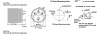
As we can see is very important to read the data sheets, then wen can know what are we installing and how to install it.
Let us know how is it going,
Let us know how is it going,
bolero
Super Member
Yes, you got that right: I just dealt with a bunch of vintage "soldering star" capacitors, that have multiple negative tabs around the outside of them. So I assumed this was the same, but with positive tabs in the center.
Glad it was something basic!
I was suspecting it might be some simple thing I was overlooking.....thanks again!!
The AU-999 is off the DBT, bias is hovering around 13mV per side. About to set DC offset again, then feed it into the 8ohm 100w dummy loads.....then hook a set of speakers up!
I wonder what I should play first. Maybe "Lucky Man" by Emerson Lake & Palmer
Glad it was something basic!
I was suspecting it might be some simple thing I was overlooking.....thanks again!!
The AU-999 is off the DBT, bias is hovering around 13mV per side. About to set DC offset again, then feed it into the 8ohm 100w dummy loads.....then hook a set of speakers up!
I wonder what I should play first. Maybe "Lucky Man" by Emerson Lake & Palmer
followed by.....Fanfare for the common man... LOUDLYI wonder what I should play first. Maybe "Lucky Man" by Emerson Lake & Palmer
bolero
Super Member
Haha! Yes!
Man....I get why ppl install multiturn trimmers in these things now. Fiddly!
Got DC offset close to 0 on both channels , but it bounces around by 5mV or so.
Hooked up the 8ohm 100w resistors & monitored bias while I turned the volume up a bit. Both channels tracked along together by the same amount. I only went up to about 15mV. I assume the bias moves around a lot, as music is playing?
I want to hook some speakers up now.
Man....I get why ppl install multiturn trimmers in these things now. Fiddly!
Got DC offset close to 0 on both channels , but it bounces around by 5mV or so.
Hooked up the 8ohm 100w resistors & monitored bias while I turned the volume up a bit. Both channels tracked along together by the same amount. I only went up to about 15mV. I assume the bias moves around a lot, as music is playing?
I want to hook some speakers up now.
perfectly normal.but it bounces around by 5mV or so.
Go for it, if the amp is not getting very hot.I want to hook some speakers up now.

bolero
Super Member
All I can say is WOW. This thing sounds spectacular!!
I had a late night listening session, throwing all kinds of material at it. Totally different animal from before. It's astounding how much all these mods have improved this amp. Along with fresh parts.
I'll replace the other old transistors too, I was getting a bit of noise from them after pushing it for a while. The 600L was doing the same, and it's next in the queue.
I can't wait to overhaul my Cornwalls. It was sounding fantastic, but they need work & the whole system will sound even better. I feel like Ken Miles with the GT40 in "Ford Vs Ferrari":
" oh YES....more of THAT, please!! She wants to go faster, I can feel it !"

Kudos to everyone here, thanks again for all the help, and all the documentation to bring this glorious gear to it's full potential!!
Cheers!
I had a late night listening session, throwing all kinds of material at it. Totally different animal from before. It's astounding how much all these mods have improved this amp. Along with fresh parts.
I'll replace the other old transistors too, I was getting a bit of noise from them after pushing it for a while. The 600L was doing the same, and it's next in the queue.
I can't wait to overhaul my Cornwalls. It was sounding fantastic, but they need work & the whole system will sound even better. I feel like Ken Miles with the GT40 in "Ford Vs Ferrari":
" oh YES....more of THAT, please!! She wants to go faster, I can feel it !"
Kudos to everyone here, thanks again for all the help, and all the documentation to bring this glorious gear to it's full potential!!
Cheers!
Last edited:
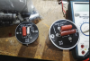
Great call on the dummy tabs Hipocrates
I've been working lately with those caps making some hats, so I had to read the datasheets.
bolero
Super Member
Another strange thing: all 3x AU-999 schems I downloaded from hifiengine are chopped off at the bottom. So I can't trace out those boards. But there's no way to report messed up files over there!
*edit* ok I found the schem here on AK, but it's not as clear a scan. At least it has that section!
FWIW the hifiengine schems are fine. For some reason my phone chops them off: I do a lot of reading on my phone.
bolero
Super Member
I replaced the two 2SC458's on 1228-1 ( TR603, 604 ) with KSC1815Y as they're on the "top 10 problem transistors list" and are likely the cause of the noise.
Old pulled 2SC458 hFE measured 97, 138.
New KSC1815 hFE measured 148, 150. Not sure if matching makes a difference, but it can't hurt?
The 2SA640's in the rest of the amp were left alone as they don't seem to be problematic.
After it passed the dim bulb test I gave it wall voltage, let it warm up & checked bias: 17mV and 13 mV across the emitter resistors. So I adjusted to 13.5mV for each side.
DC offset was still hovering between 1-4 mV on each channel so I left it as-is.
Old pulled 2SC458 hFE measured 97, 138.
New KSC1815 hFE measured 148, 150. Not sure if matching makes a difference, but it can't hurt?
The 2SA640's in the rest of the amp were left alone as they don't seem to be problematic.
After it passed the dim bulb test I gave it wall voltage, let it warm up & checked bias: 17mV and 13 mV across the emitter resistors. So I adjusted to 13.5mV for each side.
DC offset was still hovering between 1-4 mV on each channel so I left it as-is.
bolero
Super Member
I'm all over this forum like a cheap suit lately.....but another question:
I tried the headphone out for the first time & get bad hum whenever I touch a knob, or the chassis. The 2 signal wires from the headphone jack go into 2x big resistors, and then into the rats nest of wiring that presumably hooks up to the speaker outs, according to the schematic.
The balance check appears to just merge the signals from the LR speaker outs, and I was getting strange behaviour from that, too. One channel would inject static & cut out a bit.
I wonder if these are related? The headphone ground should be connected to the chassis (?? I think? ), as there are only 2x signal wires exiting the jack. But there is no nut on the front panel to hold the jack on.
Sansui headphone jacks always confused me as they don't have an external nut on them. At least none of mine do.
I doublechecked my mains 120v plug & it's wired correctly, 3 prong. Reversing the 999 plug didn't make any difference.
I tried the headphone out for the first time & get bad hum whenever I touch a knob, or the chassis. The 2 signal wires from the headphone jack go into 2x big resistors, and then into the rats nest of wiring that presumably hooks up to the speaker outs, according to the schematic.
The balance check appears to just merge the signals from the LR speaker outs, and I was getting strange behaviour from that, too. One channel would inject static & cut out a bit.
I wonder if these are related? The headphone ground should be connected to the chassis (?? I think? ), as there are only 2x signal wires exiting the jack. But there is no nut on the front panel to hold the jack on.
Sansui headphone jacks always confused me as they don't have an external nut on them. At least none of mine do.
I doublechecked my mains 120v plug & it's wired correctly, 3 prong. Reversing the 999 plug didn't make any difference.
Last edited:
bolero
Super Member
Oh: I only get the hum when a phono input is selected.
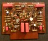
And I just replaced all the 2SC458 & 2A640 transistors on board 1228-1 with matched KSA992 & KSC1845 ( 437-439 hFE ), to try & get rid of noise & hiss in 1 channel.
I doublechecked the transistor pinouts & they looked correct. Maybe some other part on 1228 is acting up.
And I just replaced all the 2SC458 & 2A640 transistors on board 1228-1 with matched KSA992 & KSC1845 ( 437-439 hFE ), to try & get rid of noise & hiss in 1 channel.
I doublechecked the transistor pinouts & they looked correct. Maybe some other part on 1228 is acting up.

bolero
Super Member
Nope, that wasn't it.
Could it be because I don't gave a TT hooked up, and no ground wire from a TT either? The volume knob is very low, I'm not turning the volume up much. The other inputs can handle a lot more volume knob range, very quiet.
The hum is more prominent in the R channel fwiw
Could it be because I don't gave a TT hooked up, and no ground wire from a TT either? The volume knob is very low, I'm not turning the volume up much. The other inputs can handle a lot more volume knob range, very quiet.
The hum is more prominent in the R channel fwiw