

You are using an out of date browser. It may not display this or other websites correctly.
You should upgrade or use an alternative browser.
You should upgrade or use an alternative browser.

bolero
Super Member
Here's another clue: when I initially powered it up with the DBT I had my bias probes hooked up to the wrong resistor, either 855 or 856. ( although now, looking at the schematic I see they mirror 853 & 854. So you should be able to use them to set bias, too? )
Anyway I disregarded this once I realized they were the wrong resistors. But the (bias??) reading climbed up really high after powerup: to over 220mV. And didn't respond when I tried adjusting the bias pots. Then dropped back down to 0.
When I realized I had the wrong resistors, I figured it was something unrelated. But maybe it is relevant?
Anyway I disregarded this once I realized they were the wrong resistors. But the (bias??) reading climbed up really high after powerup: to over 220mV. And didn't respond when I tried adjusting the bias pots. Then dropped back down to 0.
When I realized I had the wrong resistors, I figured it was something unrelated. But maybe it is relevant?
bolero
Super Member
I have been going thru boards testing for continuity. I doubt it's on the 1159 driver boards, as I didn't replace any bias related parts other than the 1K trimmers.
The 1277, 1232 ripple current boards underneath seem the most likely culprit, as they were a pain to solder & awkward to get to. But so far all the connections seem correct & no shorts.
Will x2 check F1230, maybe I installed a cap backwards
The 1277, 1232 ripple current boards underneath seem the most likely culprit, as they were a pain to solder & awkward to get to. But so far all the connections seem correct & no shorts.
Will x2 check F1230, maybe I installed a cap backwards

bolero
Super Member
It is very strange that the bias on each 1159 directly affects the other, but inversely. And the bias only kicks in at the extreme end of the 1K adj pot. At max I can only get 3-4mV from both. If I back one off, the other goes up to 8-12 mV but no more.
I tested the traces on both 1159 boards: everything seemed to be intact. My MM had bad signals along the connector edges so I cleaned them with 99% iso, but it made no difference when I plugged the boards in again.
I guess I will start testing the original transistors C875E x2, A5326 x1 on the 1159 boards
I tested the traces on both 1159 boards: everything seemed to be intact. My MM had bad signals along the connector edges so I cleaned them with 99% iso, but it made no difference when I plugged the boards in again.
I guess I will start testing the original transistors C875E x2, A5326 x1 on the 1159 boards
Last edited:

It might be the action of the DBT (if you are still on DBT?), when you back one off, the voltage dropped is lower so you get more bias on the one channel?It is very strange that the bias on each 1159 directly affects the other, but inversely. And the bias only kicks in at the extreme end of the 1K adj pot. At max I can only get 3-4mV from both. If I back one off, the other goes up to 8-12 mV but no more.
Don't be tempted to take it off DBT just yet, because I could be wrong about the above - or something else that we don't know about might be happening.

bolero
Super Member
Oh, it's been off the DBT for a while!
I still use it to power up, after doing something. How long does it normally take the big filter caps to discharge? I get 0V across them within minutes of turning it off.
I may have found a short across cap 816 on F-1277. Small piece of solder in there.
And thanks!
I still use it to power up, after doing something. How long does it normally take the big filter caps to discharge? I get 0V across them within minutes of turning it off.
I may have found a short across cap 816 on F-1277. Small piece of solder in there.
And thanks!
bolero
Super Member
Another strange thing: all 3x AU-999 schems I downloaded from hifiengine are chopped off at the bottom. So I can't trace out those boards. But there's no way to report messed up files over there!
*edit* ok I found the schem here on AK, but it's not as clear a scan. At least it has that section!
*edit* ok I found the schem here on AK, but it's not as clear a scan. At least it has that section!
Last edited:


Post some decent resolution pictures of the work done.
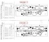
Schematic
https://i.imgur.com/LKcb11K.jpg
Another thing, if an output is shorted the DBT would be very bright.
Schematic
https://i.imgur.com/LKcb11K.jpg
Another thing, if an output is shorted the DBT would be very bright.
Last edited:
A while, you can install some dropping resistors or discharged them with a 5W resistor (100Ω to 1k)How long does it normally take the big filter caps to discharge?
Correct, my personal approach would be to get the DC conditions correct (i.e. DC Offset & Bias), before applying a signal.Ps I have not tried running a signal into the amp yet, or hooking up a load/speakers. I assumed getting a stable bias first, would be priority?
Thanks again, all!
from 2w and more, and 47Ω and more, the goal is just to discharge them without sparks, value is not critical, whatever you have there.I guess an 8ohm 100w resistor wouldn't do?
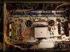
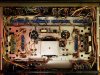
Man I don't get those 90's resolution pictures on this server, I would think that in this day and age storage would be cheap enough, but enough of my silly rants.
I can see the crowbar is still there (F1313) that's an ancient protection circuit, by this day and age it give more problems than anything IME (MAC1700 and 2 AU-999). Is that connected?
I can't see much, and I have no idea what filter caps did you use, but those wires could be connected to dummy terminal on the cap.
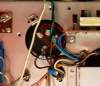
I can see the crowbar is still there (F1313) that's an ancient protection circuit, by this day and age it give more problems than anything IME (MAC1700 and 2 AU-999). Is that connected?
I can't see much, and I have no idea what filter caps did you use, but those wires could be connected to dummy terminal on the cap.
Last edited: