• The move to the new server is done. There are some software and database maintenance updates in process. This has us passing the hat around to help out. We appreciate any donations. Seriously, even a dollar helps. The payment page may be found here - https://www.audiokarma.org/support.html

AU-D9 for restoration

Hyperion

Roobarb & Custard
Subscriber
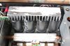
At last this beauty arrived today, it's in very nice condition as you can see. :thumbsup:

It belongs to another UK forum member, Mark - so - not mine :(

IMG_2545a.jpg

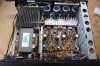
Top cover removed - Lots of Metal Oxide (MOX) resistors on the driver board and elsewhere - but no fusibles seen. ;) Ref: @P. Hageman https://audiokarma.org/forums/index...seable-resistors-in-a-au-d9-amplifier.875475/
IMG_2546.JPG

Some glue issues (note grey MOX resistors for ID purposes @P. Hageman )
IMG_2547.JPG

It will be getting a full restore, not sure if I'll be changing the main PSU capacitors, I'll see how they are. ;)
 
Last edited:
Register to hide this ad
Yes, that's what I thought too, :) I'm hoping that means it will come off more easily. :D
 
Last edited:
How are the heat-pipes generally on these ?
I've always tended to avoid heat-pipe technology(s) out of concerns for long term reliability (gas / fluid leakage)

:lurk:
 
At last the weather has cooled down, and I found some time to have a look at this AU-D9. Very clean inside, I found that 3 screws were missing from the EQ/PSU board on the right hand side, these have now been replaced. I was able to set bias and DC offset, with no problems other than the lack of sensitivity of the old trimmers. (left channel bias was ½ what it should have been ;)). The bias drift was small, and also DC offset was stable enough.

Having a listen now, it sounds very nice, it will be interesting to see how much this can be improved. ;)
 
John, looking forward in following this thread :-) In case you did not know: I am VERY interested!! Thanks for taking us on this "journey".
 
I've been auditing the components for replacement today, finding out what I need to buy to get this unit nicely sorted out. Auditing is done - just need to collate and rationalise the list of items and get them ordered. ;)
 
I removed the small section of heatsink to be greeted by this! - the definition of the heatsink compound is a bit lost in this picture, but there is far, far too much here. :) (and there were 2 more screws missing, this time from the heatsink).
IMG_2548a.jpg

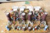
Driver board removed - ready for removal of 'glue' and rebuild (replacement components are on their way).
IMG_2549a.jpg

Since taking the pictures the four large capacitors have been removed from the board, and glue cleaning is complete. :smoke:
 
Last edited:
I have the smaller version in the garage (AU-D7 silver face/set) and had thought that the d7 and d9 shared similiar architecture (and sound).
There are quite a lot of differences between these two models, enough that you could tell them apart in a listening test I think.
Were these a feed forward design?
The AU-D9 is a Super Feed Forward design - but the AU-D7 and AU-D5 are described as 'Linear A' which seems to be a made up name for a well known, more standard looking topology.
 
Driver Board

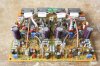
Completed with its new components
IMG_2551a.jpg

Parts replaced:-
16 Electrolytic capacitors. (2 replaced with film capacitors).
4 Trimmers.
4 Zener diodes.

I added thermal compound between the 'horseshoe' multi junction diodes and the tabs of the driver transistors, you can just see this in the picture.
 
John, what a nice interesting thread to follow!! I am still busy with the power suply EQ board, but I have to do the driver board also. Have a few questions, why did you replaced the 4 trimmers and the 4 zener diodes? (can you give me a describtion on what kind of trimmers and diodes you used)
 
Hi Peter, thank you ;) - Firstly I always replace trimmers, the originals will have oxidised inside and are impossible to clean, that is even if you assume the 'track' isn't degraded. The old trimmers also seem impossible to adjust finely and accurately, the solution - replacement trimmers. When you choose replacements you must observe the direction of adjustment - in this case 'from the top' - hence I bought Bourns 3296Y trimmers -
which:-
A). have a triangular lead arrangement. (to match the originals as closely as possible).
B). are top adjust
C). are 25 turn. (for ease of adjustment).

The zener diodes, generally don't absolutely 'need' to be replaced, although they can become noisy especially with age. So, I usually replace important or 'key' ones which gives me the chance to mount the replacements up on ceramic beads. I do this because zener diodes often get hot - sometimes very hot, and they are a voltage reference, (this is what I mean by 'key'). So anything you can do to keep them cooler and shed the heat better is a bonus, as less heat = more stable.
 
Back
Top Bottom