• The move to the new server is done. There are some software and database maintenance updates in process. This has us passing the hat around to help out. We appreciate any donations. Seriously, even a dollar helps. The payment page may be found here - https://www.audiokarma.org/support.html

Audiophile Speaker Panel of unknown origin - All Polydax. SOLVED: Fuselier Model 9

Making Progress

Speaker #1 is back in from the workshop. Here is what has been done since last time:

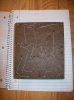
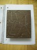
New base. I used Red Oak and was going to give it a contrasting stain but nothing looked right with the wood of the panel. Ended-up painting it semi-gloss black. Rounded-off the edges to give them a more polished look.

Took the grill cloths off, washed them and reattached. Not perfect but given the amount of cloth, saved a butt-load of nickles.

Painted the baffle and all attaching hardware satin black. Very big difference. Really made everything look new and fresh.

Put 6 coats of danish oil on the wood - front and back. Looks really good.

Still waiting on the replacement diaphragms for the low-tweeters.

Still trying to think of a name. Since there are eight Polydax drivers in each panel, I have been thinking about calling them "Octo-Dax" :dunno: Still looking for suggestions.

Haven't done much with the crossovers. Made a few sketches but I am afraid I am over my head there.

One thing I DO know is I need a better camera!
 

Attachments

  • 100_6449.jpg
    100_6449.jpg
    58.7 KB · Views: 178
  • IMG_20150109_201439640.jpg
    IMG_20150109_201439640.jpg
    61.3 KB · Views: 160
  • IMG_20150109_201706051.jpg
    IMG_20150109_201706051.jpg
    38 KB · Views: 154
You are doing right by these oddballs. They are gorgeous! I can't wait to hear how they sound once you get the diaphragms in place and the crossover sorted out.
 
...
Once the cloths were off, one grill was broken on the corner. Well, not really broken but it's joint had come apart. Take a look at this joint! I have never seen anything DIY like this. Definitely made by professional equipment. The closest I think it can be to DIY is maybe a kit.

View attachment 563847

View attachment 563848

I applied some good wood glue and used a couple of tie-downs to strap around the perimeter to hold everything tight. Should be good as new once the glue dries and cloth is re-stretched!

This is not an especially difficult joint to make. Very standard lock-miter joint that anybody with a router table can do quickly. It IS a somewhat expensive router bit, so more likely a woodworker with considerable experience built the frames, but still not conclusive as to being a kit or commercial product.
 
Very nice work, they look really nice.

How about Le Straight Eight or Le Flat Eight, ala Porsche's famous flat-8 boxer racing engine.

porsche-907-Engine-top.jpg
 
Very nice work, they look really nice.

How about Le Straight Eight or Le Flat Eight, ala Porsche's famous flat-8 boxer racing engine.

porsche-907-Engine-top.jpg

Nice! And I like "Le Flat Eight" also.

Is that your lump or a pic from the web?

About 20 years ago I had a chance at a Porsche Super 90 engine that had found it's way into a VW crew-cab bus, but alas it didn't work out. I always wanted to build a Speedster replica and put a 90 in it. In hind-site the bus would have been pretty cool to have too!
 
Last edited:
Low-Tweeters now functional

Hey Folks,

I go the replacement Audax diaphragms from Allen Organ in the mail today. Installed in about 15 minutes and they work perfectly! One more box checked.

Next on the list is to build a schematic of the crossovers. I know very little about this process so there will likely be many, MANY questions along the way.

What is the collective groups opinion: Should I start a new thread to work-out the crossover or keep it in this thread?

Thanks!
 
Keep the same thread as we know where to find you :). Once you post the
x-over schematic, someone here will fast translate it :).
 
Nice! And I like "Le Flat Eight" also.

Is that your lump or a pic from the web?

About 20 years ago I had a chance at a Porsche Super 90 engine that had found it's way into a VW crew-cab bus, but alas it didn't work out. I always wanted to build a Speedster replica and put a 90 in it. In hind-site the bus would have been pretty cool to have too!

Thanks! Man, I wish that flat 8 was mine, it is a really cool racing engine, and I'd put it into my Porsche 914/6 in a heartbeat just like the 2 914/8's in the Porsche Museum.

Nice that you have the tweeters working again. As for the crossover, start from the inputs and work towards the tweeters first - that's the easy stuff. Then try the midrange circuit. The woofers may be more complex because of the possible series/parallel connections and whether they all are tied together or are separate woofer circuits.
 
Same thread for crossover. Ask away, wish I could draw it for ya but even with pictures of front and back, it's one of those things where you have to be there to trace what goes to which components, drivers, etc.
Also, as you draw it, keep every symbol very spaced so you won't run out of room (if you need to adds component by others) and it will be easier to read when you make a final version.
 
Here is what I have so far. It is really more of the wiring side of things than the crossover proper. The BIG part is the mystery "box" in the center. That's where the fun is going to be.

A couple of things do strike me as odd/interesting however.

* Notice how the negative leg for the mids is the same signal that is used for the positive leg of the woofers. Is this simply phase inverting? I have never seen phase inversion except on tweeters.

* The woofer are divided into 2 pairs (I called bank A & B). The 2 woofers in each bank are wired in series, then the two banks are wired in parallel. So the series wiring halves the impedance and then the parallel wiring doubles it, right? What you end-up with is the impedance of the original woofer, which is 8 ohm.

* The mids are wired in parallel.

Most of inductors do not have a value written on them so I will need to figure this out. I read some about it a while back of how to measuring inductance and IIRC there didn't seem to be a straight-forward way of doing it - not like a resistor or capacitor at least. I'll need to read some more.

Any insights?
I am totally perplexed about the inputs.

If I plug into the banana plugs that driver the "RED" signal, I get full range sound from all drivers.

If I plug into the banana plugs that drive the "ORANGE" signal, I get almost nothing but the lowest bass.

If I strap the two banana plugs together, the level of highs that are produce is greatly attenuated.

DMM readings:

When plugged into Red
w/o add-on crossover: 8.0 Ohms
with add-on crossover: 6.4

When plugged into Orange
w/o add-on crossover: 8.4
with add-on crossover: 6.7

When Red and Orange are strapped
w/o add-on crossover: 8.3
with add-on crossover: 6.3

I plan to pull one of the crossovers and start documenting layout tonight.

Thanks for all the help folks. I appreciate it!
 

Attachments

  • xover.png
    xover.png
    51.6 KB · Views: 65
Here is what I have so far. It is really more of the wiring side of things than the crossover proper. The BIG part is the mystery "box" in the center. That's where the fun is going to be.


A couple of things do strike me as odd/interesting however.


* Notice how the negative leg for the mids is the same signal that is used for the positive leg of the woofers. Is this simply phase inverting? I have never seen phase inversion except on tweeters.


* The woofer are divided into 2 pairs (I called bank A & B). The 2 woofers in each bank are wired in series, then the two banks are wired in parallel. So the series wiring halves the impedance and then the parallel wiring doubles it, right? What you end-up with is the impedance of the original woofer, which is 8 ohm.


* The mids are wired in parallel.


Most of inductors do not have a value written on them so I will need to figure this out. I read some about it a while back of how to measuring inductance and IIRC there didn't seem to be a straight-forward way of doing it - not like a resistor or capacitor at least. I'll need to read some more.


Any insights?

I am totally perplexed about the inputs.


If I plug into the banana plugs that driver the "RED" signal, I get full range sound from all drivers.


If I plug into the banana plugs that drive the "ORANGE" signal, I get almost nothing but the lowest bass.


If I strap the two banana plugs together, the level of highs that are produce is greatly attenuated.


DMM readings:


When plugged into Red

w/o add-on crossover: 8.0 Ohms

with add-on crossover: 6.4


When plugged into Orange

w/o add-on crossover: 8.4

with add-on crossover: 6.7


When Red and Orange are strapped

w/o add-on crossover: 8.3

with add-on crossover: 6.3


I plan to pull one of the crossovers and start documenting layout tonight.


Thanks for all the help folks. I appreciate it!


Looks great! I still am wondering about the add on filter, if that inductor was a capacitor it would make sense. Any drivers can be phase inverted, nothing about the driver wiring hits me as strange (someone please correct me if there is) so pin 9 is ground or positive. The result of connecting to just orange makes sense because of the 400uF from signal to ground. That mystery inductor after those capacitors I'm guessing will read a huge inductance.
As far as measuring inductors, you need a LCR meter or an oscilloscope. Neither is cheap for good quality.

Don't know if I said this before, but the 4.1uF white capacitor on the main board looks out of place as well.
 
Last edited:
Not as bad to get to as I thought it would be to remove the X-Over

Someone had a sense of maintainability during design of this thing at least.

I was dreading removing all the connectors around the edge to get the crossover removed. No need to - an engineer designed this! Remove the nuts on top and the entire board lifts off as a complete unit. Brilliant.

100_6454.jpg

100_6456.jpg

Here's the front...
100_6457.jpg

Here's the back...
100_6458.jpg

Here are several of my pitiful attempts at translating the board to a schematic
100_6463.jpg

I will keep trying but I wonder if I will ever get it right?

I know it looks simple to those who know this sort of thing but I am struggling with it.
 
Last edited:
Falcon Acoustics chimes in

Being that no one had a clue where this may have come from, I sent an email with some pictures to Falcon Acoutics to see if it was something they may have seen before - after all, they have been in the DIY kit business for quite a while.

Very nice and helpful folks over there. Here is the response from Jerry Bloomfield at Falcon:


"Hi Jay and thanks. I’ve sent your pictures over to Malcolm to see if he can
shed any light on your “find”. The crossover components tell me it’s not
anything we’ve ever been involved with, I would personally suspect that it’s a
prototype, it looks too professionally put together for a kit."


I hope to hear more from them once Malcolm has a chance to look at the pictures. Again, I cannot stress how nice and helpful these folks are.

No closer to an origin but some interesting inputs.
 
The way the crossover lifts out is incredible....I for one have never seen anything like that. Keep trying on the schematics!
 
Wow! Translating a crossover to a schematic is not easy. I tried several times today but keep getting lost in the traces. I think I may have an idea that could help.

I took the picture of the back of the x-over and flipped it horizontally. Then I placed that image on top of the picture of the front of the x-over as a new layer. Played with the parallax and sizing so they would both line-up then adjusted the opacity. Exported a new picture and it's sort-of like having x-ray vision.

Maybe I can get it sorted-out now.
 

Attachments

  • front.jpg
    front.jpg
    76.5 KB · Views: 75
  • 100_6460.jpg
    100_6460.jpg
    70.9 KB · Views: 62
  • flipped.jpg
    flipped.jpg
    71.6 KB · Views: 59
  • topandbottom.jpg
    topandbottom.jpg
    53.8 KB · Views: 87
Still struggling with the schematic but one thing I have determined that is odd as hell.

The output pin on the left side of the crossover that is unused is protected by a fuse. WTH???

Given the way the crossover is mounted (easy to pull off, change, put back on), and the fact there is an unused pin that is protected by a fuse, l increasingly suspect these were indeed a prototype.
 
They have come a long way since they were found slowly rotting in a dank basement a month ago!

Too late this evening, but the audition will begin tomorrow. I have high expectations. :music:
 

Attachments

  • 100_6505.jpg
    100_6505.jpg
    70.9 KB · Views: 104
Reverb I think that you will like the sound of the Audax HD13D34H tweeters.
They were their TOTL tweeter at that time. :)
 
Back
Top Bottom