• The move to the new server is done. There are some software and database maintenance updates in process. This has us passing the hat around to help out. We appreciate any donations. Seriously, even a dollar helps. The payment page may be found here - https://www.audiokarma.org/support.html

Audire Forte 250 Build

hamrules

AK Subscriber
Subscriber
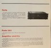
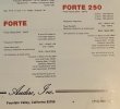
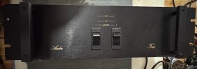
I ended up with one of these, and I see there is a Forte and the Forte 250 like this one. Anyone know what they did to supposedly double the output power. Voltage increase? I saw in some literature that the Forte was supposed to have 80,000uf per channel - that's more like per amplifier. I'm going to see about powering it up and checking some voltages especially bias so if I goof something up refreshing it at least, I have a base line for how it was. I don't find a whole lot of info on this line.
 
Register to hide this ad
Checked across the .3 ohm emitter and both sides were at 10mv. I didn’t let it warm up all the way but it was barely trying to go any higher. Probably looking at 35ma would be my take.
All the bleeder resistors for the main filter caps look cooked/cracking.
DC offset was like 95mv one side and the other started at 525mv and after a while got down in the 20mv range. From what I read online looks like the transistor array’s need replacement.
Otherwise, by looking, I didn’t see anything that looked “bad”.
 
Last edited:
I metered 113.6 volts across the transformer outputs into the bridge rectifier. I can’t safely get the voltage, yet, on the outputs of the bridge rectifier.
 
Got in there and measured just shy of 151vdc on the bridge rectifier outputs. So, it looks like 75vdc per rail.
 
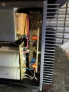
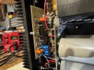
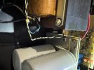
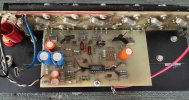
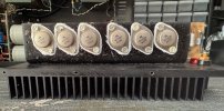
IMG_5012.jpegIMG_5013.jpegIMG_5011.jpeg
Power supply board less bridge rectifier.
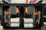
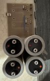
The filter caps checked out on the tester but we will see. They were from 10,250uf to 11,290uf.
 
Been digging around on the interweb and found all sorts of capacitor sizes used.
9,600uf x 4 for 38,400uf / channel
10,000uf x 4 for 40,000uf / channel
12,000uf x 4 for 48,000uf / channel
12,000uf & 26,000uf x 2 for 78,000uf / channel
Wonder which set worked the best.
 
Last edited:
Looking at the transistor array they are MPQ7051’s that are installed and not the MPQ6600. No idea if these were changed out or if because of the higher rail voltage in this 250 model. They are original Motorola with the gold plated pins.
 
Congrats on the Forte 250, @hamrules.

I've worked on about 16-17 Audire amps and preamps including a Forte which was apparently a late pre-production model.

Here are some suggestions. First, don't raise idle current to 35mA - keep it around 10-11 for now and check for crossover distortion, adjust upward to reduce/eliminate. Also, check heat sink temperature after 10 minutes of feeding an input signal sufficient for maybe 50wpc out into 8 Ohms. I suspect you may not as high as 35mA idle setting, which might cook everything. There is very little space inside this amp and the outputs are buried in there.

Looks like 6 output devices per channel? Same as the standard 125wpc version. Yes, I'd expect Julius raised the rail voltage to get there, something he did with MOSFET versions of some amps. I wouldn't be surprised if he used higher current/voltage output transistors - what are in your unit? Looks like the transformers in your unit are definitely different than the 125W version, and oriented differently.

Julius loved really stiff power supplies and used very high main cap values. If I recall, the pre-production 125W Forte had 80,000uF per channel - I can't recall the individual cap values but I ended up replacing them with slightly lower capacitance value higher voltage rated caps. Your amp has shorter caps. What are the values?

Not surprised by the MPQ7051 packages - he should have used them in a lot of his amps that ran rail voltages, even for the A versions. He had a lot of failures of the MPQ6600 over the years and ended up replacing them with matched discrete transistors with an aluminum tab glued across the tops. I pull all of the MPQ6600 out of any Audires I work on and replace them with super close-matched transistors and glue a copper strip across them with high heat epoxy. However, if yours still test closely matched, I'd definitely keep them, since they are much higher voltage-rated than the 6600.

Post more good photos as you move along with the work.

 
Last edited:
Congrats on the Forte 250, @hamrules.

I've worked on about 16-17 Audire amps and preamps including a Forte which was apparently a late pre-production model.

Here are some suggestions. First, don't raise idle current to 35mA - keep it around 10-11 for now and check for crossover distortion, adjust upward to reduce/eliminate. Also, check heat sink temperature after 10 minutes of feeding an input signal sufficient for maybe 50wpc out into 8 Ohms. I suspect you may not as high as 35mA idle setting, which might cook everything. There is very little space inside this amp and the outputs are buried in there.

Looks like 6 output devices per channel? Same as the standard 125wpc version. Yes, I'd expect Julius raised the rail voltage to get there, something he did with MOSFET versions of some amps. I wouldn't be surprised if he used higher current/voltage output transistors - what are in your unit? Looks like the transformers in your unit are definitely different than the 125W version, and oriented differently.

Julius loved really stiff power supplies and used very high main cap values. If I recall, the pre-production 125W Forte had 80,000uF per channel - I can't recall the individual cap values but I ended up replacing them with slightly lower capacitance value higher voltage rated caps. Your amp has shorter caps. What are the values?

Not surprised by the MPQ7051 packages - he should have used them in a lot of his amps that ran rail voltages, even for the A versions. He had a lot of failures of the MPQ6600 over the years and ended up replacing them with matched discrete transistors with an aluminum tab glued across the tops. I pull all of the MPQ6600 out of any Audires I work on and replace them with super close-matched transistors and glue a copper strip across them with high heat epoxy. However, if yours still test closely matched, I'd definitely keep them, since they are much higher voltage-rated than the 6600.

Post more good photos as you move along with the work.
All I did was measure across emitter resistor (.3 ohm) and that was 10mv (both sides) so that is how I came up with 35ma.
This one has 4 caps at 10,000uf / 75volt - 95volt surge. I feel that voltage rating is a little low.
I will be taking apart further then I can get more pics and see what outputs are in it.
Both channels have a DC offset issue going on and I just figured it was that transistor array I see talked about online. That's how I saw the different one used. I was thinking of maybe using MPSA42 & MPSA92 in a socket instead of soldering right to board. Like G.A.S. did.
 
All I did was measure across emitter resistor (.3 ohm) and that was 10mv (both sides) so that is how I came up with 35ma.
My mistake - I misread your post. Yes, 10mV across those 0.3R sounds about right. I don't have my notes handy but now I seem to recall that is about where I landed. Apologies. Still, I'd bring it down and ramp it up based on heat sink temp and crossover distortion.

DC offset is a problem with these amps and all of the Audire amps I've worked on. Those quad diff packages were never precisely matched and they drift with heat/voltage/current, and unlike discrete JFET diff pairs he used in some preamps, there are no trimmers for DCO. As I mentioned, I just replace them with very tightly matched MPS8099/8599, which is what Julius used. I rebuilt one amp using socketed diff pairs - works well. Gain is higher than MPSA42/92, and they are faster parts, but lower voltage.
 
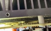
IMG_5020.jpeg
Right to the left of that hex head screw there’s the bias transistor. Is this glued to the heatsink? I hate to pull these boards apart and trash that transistor.
 
Interesting. WRT the 125W version, same board layout and I can't tell from the low resolution photos, but perhaps same component values on the boards. Same outputs as well, same quantity, so Julius must just bumped up power with higher rail voltages and bias. Must run hot.

Looking over my notes, I played with idle current settings between 25 and 50mA per device and settled at 33mA based on distortion measurements and heat sink temp.

The bias transistor is just bent to make good contact with the heat sink and coupled with paste. Removing the input board won't damage that transistor. No problem if you have to replace it anyway.

On the pre-production one I rebuilt, the drivers were also just pressed against the heat sinks with mica insulators. I ended up drilling/tapping holes and mounting them more securely. I also had to hand-file the L bracket to fit totally flush with the heat sink.

Of course, replacing the electrolytic caps is a good idea. I've also found a surprising number (albeit fairly low percentage) of those monolithic polyester caps that have gone out of spec in these amps, probably due to heat. Most of the other passives seem to fare well.

Confirmed this one had 80,000uF with a combo of cap sizes and values to fit the space. I replaced with 4 x 20,000uF Kemets and since they were shorter, made a spacer block that fits under the retainer strap.

I also replaced all of the output transistors with nicely matched parts. I buy a couple hundred at a time and match sets on my Tektronix 577.
 
I was basing the MPSA42/92 on the MPQ7051 which has low HFE and is slower. I get confused with these things.
I was thinking on going to 4 @ 16,000uf since they are longer 105mm vs 82mm.
 
I speculate that the decision to go with MPQ7051 was solely based on the higher Vceo for these higher rail voltages. The MPS8099/8599 are 80V parts, so pretty close to the rail voltages. You may be on the right track with the MPSA42/92.
 
Or, maybe consider 2N5401/5551? Vceo is 150V, fT is 100-300.
MPS8099/8599 were close in fT range to MPQ6600.
 
Back
Top Bottom