

You are using an out of date browser. It may not display this or other websites correctly.
You should upgrade or use an alternative browser.
You should upgrade or use an alternative browser.
Audire Forte 250 Build
- Thread starter hamrules
- Start date

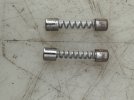

Yes, a few of them actually.Yikes. I've never seen those either, and would not trust them. Good riddance.
If the screws are too long you can trim them. Do you have one of those multipurpose wire stripper/crimper pliers with the screw cutters?
I’m getting high temp high strength plastic screws so I don’t have to deal with insulating the metal screws.
Last edited:
I’ve got the I/P differential pairs sorted out last night. 2N5401 & 2N5551, matched VBE & HFE, also have new drivers & outputs.
Have to figure out a couple “poly” caps with no labeling.
Also have some low profile head screws coming for the heatsink so there’s a little more gap between them and the board.
Have to figure out a couple “poly” caps with no labeling.
Also have some low profile head screws coming for the heatsink so there’s a little more gap between them and the board.
I keep forgetting, should these be normal or slow blow.View attachment 3825593
Here’s a picture of the crazy fuses installed in it. What in the world.
I’ll try.Nice.
Which poly caps are you referring to? If you want to post pics I'll take a look, but make them high-res, not like what you've been posting, please.
I happen to have those 5A in FB.In the 125W version, these are 5A FB.
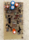
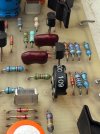
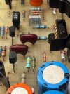

Those are Mica caps. I can't recall the value and don't have the amp, but looking at their position on the board and their apparent location in the schematic, I'm going to say 10pF. In some models they were 5pF, but I think these are 10pF. Make sure these are good.
Last edited:
Reviewing your initial posts...
Do replace those main filter bleeder resistors. What value and wattage are they now? Maybe bump them up in wattage, and definitely mount them off the boards.
Do replace all of the electrolytic caps, including on the clipping indicator board.
Do replace those main filter bleeder resistors. What value and wattage are they now? Maybe bump them up in wattage, and definitely mount them off the boards.
Do replace all of the electrolytic caps, including on the clipping indicator board.
5.6K, not sure on wattage, I’d guess 2 max maybe just one watt. I’ve ordered 3 watts just so they fit easy.Reviewing your initial posts...
Do replace those main filter bleeder resistors. What value and wattage are they now? Maybe bump them up in wattage, and definitely mount them off the boards.
Do replace all of the electrolytic caps, including on the clipping indicator board.
I forgot about that clip board.
I took them out. One 29pf the other 32pf. I think both 10pf as that schematic just had the RCA input.Edit...
Pull a leg on each and test with your capacitance meter. In one schematic they are both 10pF. In another, the one connected to the 1k is 5pF.
Yes, 5k6 looks right. In the ones I've worked on they were only 1W; go with 3W. That's what I've done with the amps I've rebuilt. I have a standoff leg crimping tool but you can do it with fine needle-nose pliers.
Probably both are 10pF. If you don't have a very good LCR meter it can be difficult to get an accurate reading down that low. That's why I have several good LCR meters! Use Mica or polystyrene, not polyester.
Probably both are 10pF. If you don't have a very good LCR meter it can be difficult to get an accurate reading down that low. That's why I have several good LCR meters!
Use Mica or polystyrene, not polyester.
I’ve gotten pretty good with needle nose pliers bending legs around.Yes, 5k6 looks right. In the ones I've worked on they were only 1W; go with 3W. That's what I've done with the amps I've rebuilt. I have a standoff leg crimping tool but you can do it with fine needle-nose pliers.
Probably both are 10pF. If you don't have a very good LCR meter it can be difficult to get an accurate reading down that low. That's why I have several good LCR meters!
Sounds like some new mica’s will be coming in.
Might just leave them alone. I can’t budge those Allen bolts on the handles. Good grief they are tight.I noticed the rubber washers for the transformers are looking a little dry and cracking. Might need to replace them.