You are using an out of date browser. It may not display this or other websites correctly.
You should upgrade or use an alternative browser.
You should upgrade or use an alternative browser.
Audire Forte 250 Build
- Thread starter hamrules
- Start date
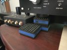

Have some 1” tall feet coming. Should be able to fit them fairly easy. Probably use a PEM nut on the bottom cover.
Drilled the output cards locating holes to 1/8” to match the dia in the L brackets. Two drill bits will work fine for installation of outputs for alignment and then just remove.
Shout out to @GKTAUDIO for all the help so far.
Drilled the output cards locating holes to 1/8” to match the dia in the L brackets. Two drill bits will work fine for installation of outputs for alignment and then just remove.
Shout out to @GKTAUDIO for all the help so far.
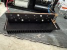


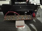
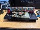
Output module back together. Man that heatsink is thick, oops ordered wrong thickness material.
The screw holding the I/P board to the heatsink was 1/2” just a tad too short, I had a 5/8” and yes a tad too long. Little trim job and all good. The little things can sure slow you down.
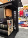

That copper is way thick.
Also, I strongly recommend you ditch the diff pair socket and solder the transistors closer to the board. It is likely to oscillate like this. Also, the weight of the copper may stress the legs.
These are high bandwidth amps and were prone to oscillation when new, so best not to add to that risk.
Also, I strongly recommend you ditch the diff pair socket and solder the transistors closer to the board. It is likely to oscillate like this. Also, the weight of the copper may stress the legs.
These are high bandwidth amps and were prone to oscillation when new, so best not to add to that risk.
I’m bummed.That copper is way thick.
Also, I strongly recommend you ditch the diff pair socket and solder the transistors closer to the board. It is likely to oscillate like this. Also, the weight of the copper may stress the legs.
These are high bandwidth amps and were prone to oscillation when new, so best not to add to that risk.
It looked cool with that huge chunk of copper, ha ha.
Last edited:

I’m going to see if I can get that heatsink separated from the transistors. If not it’s back to transistor testing for another set. At least the tester is fixed as a test lead end broke off it last time.
Going to try 14ga thickness, that’s about a 1/16” thick.
How the heck do you get all those transistor pins into the holes at one time. Some kind of trick perhaps.
Going to try 14ga thickness, that’s about a 1/16” thick.
How the heck do you get all those transistor pins into the holes at one time. Some kind of trick perhaps.
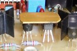
That looks nice. You even cut the corners on an angle. I have to step up my game now.Here's how I do them.
Using the solderless breadboard, you'll see the need to skip one socket between transistors in one aspect , and one row of sockets in the other. Leave them in the breadboard until the epoxy cures.
View attachment 3830823