• The move to the new server is done. There are some software and database maintenance updates in process. This has us passing the hat around to help out. We appreciate any donations. Seriously, even a dollar helps. The payment page may be found here - https://www.audiokarma.org/support.html

Audire Forte 250 Build

The AC breaker/on-off switch provides the lag you need for the overall power supply and circuit. You want fast blow fuses on the amp boards, not slow blow.

The Noble II is a 200WPC A/B amp and it uses 4 - 3A fast blow fuses. Somewhat possible you will need 6A fast blow in that amp.
 
Depends on the model and production period. The early preamps were very good but not what I'd call exceptional, but later ones had better topology and more sophisticated active devices and sound excellent. My Andante is simply outstanding, and I've got many other high-end preamps from the same era (Threshold, Spectral, Mark Levinson, Counterpoint and more).

Good starting point is a later Legato.
 
Well, we will see how it fairs as we move along. I'm only doing the one channel first so I can check it out and see how it works out.
I did find the MPQ7051, maybe I would just be better off getting them?
I ordered the 6 they had left in stock. More goodies for the coming week.
 
Earlier versions used a metal can op amp, and had reed switches. Balance control on the right side of the panel. Stacked PCB, and some other details.
Later ones had volume and tone controls next to each other on the left, single large PCB, plastic DIP8 op amps, and a DPDT Coto relay.
Between these two there was a run with the Coto relay, so changes to the PCB to accommodate.
Aesthetics are pretty similar, but performance of the later ones is better according to my QA403 and Audio Precision analyzers, as well as my ears.
I can't attach photos for some unknown reason. Look for an incoming PM...
 
IMG_5042.jpeg
Forgot, came with original box. Surprised it didn’t disintegrate. Not sure if I should put it in the attic above garage or toss.
 
If you have room, keep it - very cool to have the original box. You can always stick it in another box in better condition if you sell or move it.
 
If you have room, keep it - very cool to have the original box. You can always stick it in another box in better condition if you sell or move it.
When it came it was in another box. I think you could have put three of them in this giant box they sent it in.
 
IMG_5057.jpeg
Thermal paste and low profile socket head screws. Also test fitting the new threaded holes (6-32) for the two transistors. We should have better clearance and better holding of the TO220’s.
Oh, the Phillip screws are high temp (500deg) / strength plastic.
 
Last edited:
IMG_5062.jpegIMG_5061.jpeg
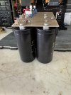
PS board back together. Drilled a larger hole for the new bridge rectifier so it fits nice. I’ll probably mount the board and then install the transformer wires to the bridge. Good thing they made them short enough so it would be easy - NOT.
 
IMG_5063.jpeg
Back together. New red wire and 0v transformer wire. Had to heat shrink one AC lead that had a cut. For the other side I need to tin the bridge rectifier connections, that would have made it go way faster & easier.
 
IMG_5065.jpeg
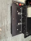
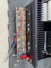
Output board with new parts. This is crazy, you have to align all the T03 mounting holes and put a few screws in to hold it in place. I decided to install all screws to make sure. Well 3 of the bottom screws are going to ground. After some tinkering it seems that one of the “bushings” for the interlock to the input board is touching the heatsink when you tighten the screw. Why 50lbs of stuff stuffed into a 10lb bag if you will. I could see cutting some short pieces of heat shrink for all the screws, not a big deal just to make sure. The real issue are these connector bushings or female half whatever it’s called. I need to ponder what to do. First thought is insulating paper, that should work I’d think.
 
Looking good, John.

There are supposed to be plastic bushings around all or at least one each of the screws to index the parts to the L bracket holes. I use aquarium airline tubing cut to length. Heat shrink is a bit thin for my view of the safety margin, since it can get easily cut by the threads.

There are supposed to be fiber washers glued to the bottom of those threaded bushings that are soldered to the board, like this:

GKTAudio_Audire_Forte_Boards.jpg
 
Looking good, John.

There are supposed to be plastic bushings around all or at least one each of the screws to index the parts to the L bracket holes. I use aquarium airline tubing cut to length. Heat shrink is a bit thin for my view of the safety margin, since it can get easily cut by the threads.

There are supposed to be fiber washers glued to the bottom of those threaded bushings that are soldered to the board, like this:

View attachment 3828894
Bushings are there and glued on. No plastic bushings. Will make something. Going to take apart and figure out what is touching & why.
 
Ok, I happen to have some heavy duty heat shrink tubing that I cut and it works good.
I took a 6” scale and went across the big bushings. It turns out that a couple of those little bushings for the other board & the B & E of the T03’s are just a literal hair thickness below the big bushings. So when you tighten the screws they touch. I would think those big fiber washers over time have compressed just enough to let this happen. The easiest fix I see is to add another washer which I tried and it works just fine. Now to go find and order some.
 
Hi John,

I'm getting confused using the word bushing for both the black fiber washers and the clear plastic tubing that slips over the screws securing the output transistors. I'm being pedantic, perhaps, but do I understand that you have found some of the black fiber washers that are being used as spacers have compressed? I found that with several of the Audire amps I've worked on and bought new ones. Unfortunately, I am not on my main computer so can't look up the part number, and my box of Audire parts is not available until tomorrow.

You might be able to buy thicker fiber washers rather than using two for each position.

For your consideration: The standard 125W version generates a lot of localized heat - that 10lbs. packed into a 5lb. package thing again. The 250W version will generate more. You might consider installing 1" tall rubber feet with screws into the bottom of the chassis, or at least (and what I do) use the equipment vibration damper pads beneath those stupid stick-on rubber feet so popular with some manufacturers at the time (Audire, Apt to name a couple). I measured a 13F difference in heat sink temperatures between just using the standard feet and putting the amp on 1 pad at each corner. Good 'ol convection!
 
Yes, some of the black fiber washers have compressed just a tad.
Yes I found some heavy duty heat shrink that I cut to use in the screw holes.
I’m good with adding / stacking another washer on top of the black fiber washers that are there. They are glued and holding just fine so I’d rather just add on top.
Funny, I thought the feet looked too stubby. I’ll have to work that out. I’d be concerned about screwing something on and hitting the outputs.
 
Back
Top Bottom