• The move to the new server is done. There are some software and database maintenance updates in process. This has us passing the hat around to help out. We appreciate any donations. Seriously, even a dollar helps. The payment page may be found here - https://www.audiokarma.org/support.html

B&K ST-140 RECAP BOM

I just plugged a power strip to the variac, the multimeter plugged into the power strip and set to volts, and the amp plugged into the same power strip. I slowly raised the voltage or dropped it to where I could hear the sound; 2.7 volts is all I needed to hear sound,or about the same as a AA battery.
 
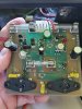
Thanks for the additional details raycarr00, all useful. I replaced C5 and C6 with good Illinois Capacitor film caps, and tested to see what current was being drawn while still connected to the limiter/variac set up. From what I can tell, there's still too much draw, and I'll be damned if I can figure out why. I've attached an annotated pdf of the test set up. We'll see where we go from here, but I'm running out of ideas. I'll upload some close-ups of the right board this weekend for you to look at. It's pretty frustrating since there's just not much to this beast.
Be safe,
jrh
 

Attachments

From the PDF, it looks like you're trying to adjust the bias. See B K bias & DC adjustment below. Did you replace the potentiometers(pots) for bias adjustment? Otherwise, the mA will continue to run high as you turn up the variac. I had the same issue. There are several resistors and what looks like white capacitors(fusistors?) under the MOSFETs; I'd check those, too. J50 MOSFET should be located right next to where you have "R" written on the board.

B K bias/ DC setting procedure: "1. Plug the amplifier into a variac. Monitor the (-) negative rail of each channel by removing the fuse and placing a current meter across the fuse clips.
2. Connect an 8 Ω load to each channel. Supply an input signal of 100 mV RMS @ 20 Khz.
3. Slowly turn the variac up to operating voltage while monitoring the rails for excessive
current draw. The meters should not read more than 400 mA DC. If one or both read
more than 400 mA, turn the bias pots (P2) to minimum and retry.
4. Set bias of the amplifier by adjusting the bias pot (P2) mounted on the solder side of the
board to achieve a reading of 200 mA on each channel for models ST 140, ST 140M,
ST 202, and ST 202+. The bias for the Pro 600, EX 442 and M 200 amplifiers is 250 mA.
Setting the bias higher than stated only causes the amplifier to run hotter and burn out
faster. It does nothing for the sound quality of the amplifier.
5. Set the DC out of the amplifier by monitoring across the outputs. Adjust the DC pot (P1)
for 0 VDC ± 5 mVDC.
Thank You, B&K Components, Ltd."

 
Last edited:
From the PDF, it looks like you're trying to adjust the bias. See B K bias & DC adjustment below. Did you replace the potentiometers(pots) for bias adjustment? Otherwise, the mA will continue to run high as you turn up the variac. I had the same issue. There are several resistors and what looks like white capacitors(fusistors?) under the MOSFETs; I'd check those, too. J50 MOSFET should be located right next to where you have "R" written on the board.

B K bias/ DC setting procedure: "1. Plug the amplifier into a variac. Monitor the (-) negative rail of each channel by removing the fuse and placing a current meter across the fuse clips.
2. Connect an 8 Ω load to each channel. Supply an input signal of 100 mV RMS @ 20 Khz.
3. Slowly turn the variac up to operating voltage while monitoring the rails for excessive
current draw. The meters should not read more than 400 mA DC. If one or both read
more than 400 mA, turn the bias pots (P2) to minimum and retry.
4. Set bias of the amplifier by adjusting the bias pot (P2) mounted on the solder side of the
board to achieve a reading of 200 mA on each channel for models ST 140, ST 140M,
ST 202, and ST 202+. The bias for the Pro 600, EX 442 and M 200 amplifiers is 250 mA.
Setting the bias higher than stated only causes the amplifier to run hotter and burn out
faster. It does nothing for the sound quality of the amplifier.
5. Set the DC out of the amplifier by monitoring across the outputs. Adjust the DC pot (P1)
for 0 VDC ± 5 mVDC.
Thank You, B&K Components, Ltd."

Hey raycarr00, TGIF!
I don't think I'm explaining the situation well enough. Maybe I'm missing something, but I WISH I was at the stage of being able to adjust the bias on this thing. Every component on the boards has been replaced, including the pots. The only things I haven't replaced at this point are the main filter caps, and they are working well. My friend, I've got a dead short here, it's that simple. I knows 'em when I sees 'em, even as I can't figure it out.

If it were component level in origin, it seems highly unlikely that such a failure would occur on both boards, yet both boards, when hooked up independently, produce the same outcome, i.e. too much current, a dead short. I even diagrammed the schematic for the power supply trying to figure it out. (Maybe I'll clean that up and post it to the forum for critique). Like I said, I'll send you a couple pics of the right board over the weekend in close up views.

Anyway, I'm determined to solve this, I don't want to put it away in dis-repair, but I've got a number of other projects I want to get to, and this thing is clogging up the bench until I figure it out. Thanks for all the comments!

jrh
 
Make sure the bias pots are turned all the way down and then give it juice; see what it reads. Also, make sure the pots are oriented correctly. If they're not, you'll need to turn the screw the other way. Check the soldering in that area and the traces. Otherwise, if both boards are giving the same results, check elsewhere. Maybe the wiring that goes towards the rectifier board. My MOSFETS are reading between 95-100+ deg. Fahrenheit on both channels and after 30 minutes.
Yes, "the pain, the pain!" Not "the plane, the plane"(Fantasy Island)....
 
Hey raycarr00,
Hope your weekend was good. I've uploaded a couple annotated shots of the right board for reference. Anyway, in pondering your suggestion of turning the pots "all the way down" it occurred to me to ask the question - "Do I not want to turn them such that they are at MAX resistance? I.e. 500 ohms? I currently have them set for about 250 ohms. It seems to make sense to do that, but what do you think? The head scratcher with all this, is the fact that both boards behave the same way independently, which suggests something common to both, not a component on the board. In they end raycarr, you may be right, that the amp is good to go and just needs to be re-assembled and adjusted properly. We shall see! Maybe chrisP2 will see this thread and weigh in, as always, all constructive comments are appreciated. Best,
jrh
 

Attachments

Those boards are definitely delicate. I looked at one of your boards up close and would have to compare with my own(will do so), but they look like they could use a more thorough cleaning with a brush and alcohol to remove those tiny solder pellets. I like to make sure there are no solder bridges by running an object in between the solder points and using a magnifying glass to assure so.
I got NOS GE/RCA for one set of bipolar transistors and Motorola for the other versions( Bipolar Transistors 2N3440, 2N5416).
The Fairchilds did not correspond with data sheet.
Make sure the resistors by the pots read right.
I would begin slowly raising the variac with the pots turned all the way down and see what mA read. If the reading jumps all over while turning the pots, try different ones( bourns).
I use a digital thermometer to monitor the MOSFETs (they're reading 95-100+ deg. Fahrenheit on both channels and after 30 minutes).
 
All good thoughts, thanks!
I'm an old guy for sure, and my eyesight aint what it used to be, but I see no solder pellets anywhere on the board here on the bench.There's some weird bubbling and distorted solder mask or conformal coating thing goin' on, but that's been there from the beginning. These are pretty crude boards by todays standards. Anyway, I'll keep punching at it. Be safe,

jrh
 
I'm rather blind; I use reading glasses on top of my prescription glasses( +3.50 for a buck at the dollar store). They bring things significantly up close. None solder bridges are significant and should be eliminated. I would begin slowly raising the variac with the pots turned all the way down and see what mA read. Apart from that, and assuming the bipolar transistors and resistors by the pots are okay(to spec). You should be safe at under 4 volts for sound. I added 10,000uf/100v caps in parallel, to my current can caps. The music persists even after the amp has been shut off. The can caps by themselves did not. The bass is not as harsh now. Sound is more defined to my ears playing Dave Brubeck's The Essential 360.
 
Hey raycarr00, looking forward to getting back to the 140 over the holiday. I'm going to give the current test another shot. In reading your last comment I am puzzled by this sentence, which I've copied: "None solder bridges are significant and should be eliminated." Please clarify. I have examined for solder bridges thouroughly with a backlight. No solder balls, no bridges, I've checked for all of that, on both boards. But I will persevere! I think I'll hook it back up to the heat sink and test it in place this time.

Interesting to hear that you've added capacitance to your unit. When my 140 was working, the sound did sustain for a brief period as the amp discharged. My caps are 15,600 uF each and yours look to be the same ones. Is it possible they have lost some ability to store charge? I guess it is. Hmmmnn.
I dicovered that they are wired in series when I diagrammed the power supply. I had just assumed for some reason that they were in parallel, but not so. An ESR test on them revealed that they are beginning to turn into a more resistive load on the circuit, not much, but defineately there. I think I'll consider replacing them, I don't want to be back in this thing. Anyway, thanks for the comments and I'll keep you posted.

jrh
 
From my point of view, there appears to be solder pellets and cross soldering. Certainly, you have taken care of the matter. I don't see anything out of the ordinary, otherwise. I still have all the original transistors, minus the MOSFETS, for your use and if you want them. Just message me.
 
Hey raycarr00,
What a gracious offer, I really appreciate that. I'm covered for the parts though, so thanks! I might be making some progress with the testing. The current test on the right board was promising with the Pyer potentiometer, P2, turned all the way down. It read about 38mA @100V AC. No limiter light shined. I'll keep you posted.

jrh
 
Hello, JR,
I am studying the schematic. Just trying to understand how this amplifier works. My be i am missing something but adjusting P2 to zero should give the lowest bias. Right? May be 250ohms is already too high and your dim bulb goes stays bright. To me Q8 with the Led and the 66ohm resistor R10 look like a current source, of some 18mA.This passes trhrough P2, so it establishes a higher voltage at the gate of the N channel mosfet, relative to tge P-channel Mosfet. Thus, larger resistance on P2 means higher bias current. Is this correct?.
The datasheet fir the 2KJ135 and 2SJ50 show that you will get about 200mA of drain current when the gate voltage is 0.7 volts or so. May be one can measure the gate voltages to see if it too high to help setting the amplifier in a safe starting point.
How many Mosfets per channel are there in the ST-140?. By the way, I blieve the JP and JN J+ J- and JO points are for soldering jumper wires to parallel an additional pair of power mosfets.
I hope you find where the short circuit is.
Good luck!
 
Hey JoseHH, Thanks for weighing in. I believe your analysis is on the right track. The ST-140 has 2 output mosfets per side. Thanks too, for the heads up on the mysterious JN,JP, and JO points. That now makes perfect sense because in the same era, B&K made a higher powered big brother to this amp, the ST-202, which was exactly as you describe, two additional mosfets per side hooked up with jumper wires. The rest of the amp topology was virtually identical. Your comment about R10 is also interesting. On the schematic I have, R10 doesn't even show up, but I figured out where it was by tracing the path on the boards and drew it in on my schematic. The interesting thing is that it was 20 ohms, not 66, so I may have an issue there as I replaced it with a new 20 ohm. I have heard that there are several versions out there of the ST-140 schematic. I'd love to examine the one you have for comparison. If you could forward an image it might prove very useful.
I am beginning to feel like I do have an over biased condition causing excess current flow, so I'm setting things up now to test that. I plan on adjusting the bias pots while the amp is on and see what I can learn. Thanks very much for the input!

jrh
 
Hello JR,
I am looking at the schematic for the st-202 which i downloaded from electrotanya (appears within the model EX-442) but it seems almost identical to the one shown above in this thread. Please see attached. I do not have an amplifier like this, i. am studying it just out of curiosity.
 

Attachments

Greetings all B&K watchers.ST-140 update:
So.......... I set things up to try to set the bias. Left board un plugged, DMM across the neg rail fuse holder of the right board. Meter set to measure mA. Unit is powered through the dim bulb and the variac. No input signal was being fed in at this point. I was just going to see if I got any life across the fuse holder before inputting the recommended tone and adjusting the pot.

I slowly raised the variac voltage up. NO current showed on the meter, and at around 30V the mysterious resistor R10 let out the Magic Smoke! WTF? as they say.

R10 is between the collector of Q5 and the base of Q8 on the schematic (I had to draw it in on mine, it's on the board but doesn't show up on my version of the schematic). R10 is now measuring open, so back to the soldering station before I do anything else.

I suppose I could still be looking at a grossly out of bias setting causing this, but I am definitely stumbling around in the dark on this thing. Stay tuned.

jrh
 
The R10 i was referring to is not that one. There are small numbering differences between the two schematics. The resistor you are describing is not in the schematic then.
 
If Q2 & Q3 test good but somehow became no longer matched would that be enough to stop sound from that channel?
I thought that a transistor never changes its specs. Either it works as new or it don't work at all.
 
Back
Top Bottom