• The move to the new server is done. There are some software and database maintenance updates in process. This has us passing the hat around to help out. We appreciate any donations. Seriously, even a dollar helps. The payment page may be found here - https://www.audiokarma.org/support.html

B&K ST-140 RECAP BOM

could be weak or out of spec. The original ones my amp had test good, but their age. so, I replaced them with new ones. They're quite affordable to not do so. having everything apart, might as well replace everything you can. 522-ZTX795A, ZTX795A Diodes Incorporated Q2 Q3 Q7(output stage per schematic) Bipolar - BJT PNP Super E-Line. $1.07 each or 89c each for 10 at mouser.
 
The R10 i was referring to is not that one. There are small numbering differences between the two schematics. The resistor you are describing is not in the schematic then.
That's correct, and after working some more on things, I think I'm beginning to understand why it was added. See update posted separately. Thanks for studying this thing Jose, it's helped.

jrh
 
Hey fellow B&K folks, ST-140 update here:
All of this dialogue has been very helpful, little clues embedded in every post! I actually feel like I'm getting somewhere. Gregs adventure with the 202 has been illustrative, as well as rays comments throughout the discussion.

It does appear, at least for now, that you can have the bias pots SO hot, that the circuit acts like a dead short. I have to say, I've never seen that before, but that does appear to be what's happening. After replacing the torched R10 resistor, I turned the pot almost all the way the opposite direction, and was able to get a reading that was more like you would expect. I think when I had the meter set to mA originally, I didn't see any current because it was out of range! When I switched to Amps, I got a reading I could comprehend. I've now got both boards reading around 175mA, so I'm confident I can try the B&K bias procedure as published. I'll put an 8ohm load on her and inject a 20kHz signal now, and see if I can tweak things up to 200mA. Fingers crossed.

I'm now thinking that R10 was added after the original schematic was drawn, or maybe it was just an oversight. In any case, it seems to be where it is, precisely in order to protect the circuit from knobs like me who try to plug it in with the bias so hot! Thanks for all the comments folks!

jrh
 
Great news! now you got some encouraging results. I suspect that P2 was paralleled with a 475ohm resistor to limmit the maximum current in case that the wiper on p2 looses contact with the track. The maximum resistance that you will get with 500//475 ohms is about 240 ohms. Thus, if p2 is connected as shown in the schematics , i think that in this amplifier one should start with P2 in the position that minimizes the resistance between the pins tgat are at the two ends of the track of p2.
 
Last edited:
:beerchug:
Definitely begin setting bias with the POT turned completely down and while incrementally raising it and the variac. Monitor the temp of the MOSFET.
In my case, with Bias set, after 30 minutes and at 120v, my MOSFETs read about 95- 100 deg Fahrenheit.
The voltage set by your electric company will determine where your bias will fall at. So, set your bias accordingly.
There are many versions of the ST 140 but just one free schematic out there(that I've found). So, copy the other board if you don't have the necessary schematic.
 

Attachments

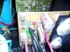
  • IMG_20200913_174658.jpg
    IMG_20200913_174658.jpg
    97.4 KB · Views: 76
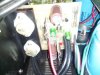
  • IMG_20200913_174640.jpg
    IMG_20200913_174640.jpg
    96.6 KB · Views: 75
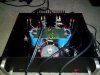
  • IMG_20200913_174619.jpg
    IMG_20200913_174619.jpg
    95.6 KB · Views: 75
Exactly, @raycarr00, but my concern is that deleting the 475 ohms resistor in parallel as the first post in this thread states, is very risky, because the maximum bias current would be twice that on the original design.

I am not sure if JR omitted the 475 resistor in parallel with P2 or not. If he did, setting the position of P2 to 250 ohms as JR stated, is equivalent to a bias current that ecxeeds the maximum bias current in the original design since with the combination of a 500ohms trimmer and a 475ohms resistor in parallel, the maximum resistance is 242 ohms. So this will cause the conduction of a large current the mosfet push-pull stage and the observed trip of the dim bulb tester.
 
Agreed. It doesn't appear that JR Harley omitted the 475 resistor, though. Just that he set the bias POT prior to raising the variac/voltage. Unless one is feeling adventurous, follow what the engineers designed- keep the schematic as is.
 
Agreed. It doesn't appear that JR Harley omitted the 475 resistor, though. Just that he set the bias POT prior to raising the variac/voltage. Unless one is feeling adventurous, follow what the engineers designed- keep the schematic as is.
Not to worry guys, the 475 is still there. I find it very interesting that the bias can run away like it does even with that resistor in parallel. Haven't had a chance to fully set up yet, but I'll let you know how it goes. And thanks again for all the comments!

jrh
 
B&K watchers - Epic ST-140 project report here:
Well, I'm actually beginning to think that we have the bus back between the white lines at this point. At 119V AC, pretty close to the wall average, I've got both boards hovering at around 200mA, and the heat sink is just pleasantly warm. What a tweak-o-thon! Next step is to put the fuses back in and let it burn in for a while, as well as look at a signal on the scope. Whoo-Hoo!, now I can look to the fun stuff.

I'm considering replacing the main filter caps. They test pretty good as best as I can do it, but they are 40 years old, simple as that. I have been beatin' on this amp for over 3 years, off & on. I'm thinking I don't want to come back in here. Anybody know of the ideal replacement? I've got some options so far, but any suggestions are always appreciated. Feelin' pretty good about things at this point, so again, thanks for all the feedback guys.

jrh
 
Excellent news!. Great to know that you managed to tame the idle current. DC offests adjusted without problems?.
 
:beerchug:JR Harley, what temperature are your MOSFETs reading at 200mA, with the voltage set at 119v and after how many minutes on? You can spend a lot of money on filter caps, but you can also save a lot, too. I got these for 7 bucks each (including shipping)and added them in parallel to the existing caps: Nichicon Electrolytic Capacitor, 80V 15000 uF, NR Series(google them). They're NOS and will need reforming. I tried 60v versions but they literally popped, smoked and oozed. So, the higher the voltage, the better.
 
Hey B&K guys, I've just taken a pause here to plan and do a little research etc. Currently basking in the satisfaction that comes from fixing things. (Although I won't be toasting the success just yet, not until I've got it back up in the rack. This thing has fooled me too many times before!) I bought this amp new in '83 or so, and want to put it back together in "good Nick", as they say, so I'm pondering a few things and doing some houskeeping on it.

I had been testing the amp with the MOSFETS from Newark, but I'm going to replace them with my previously sourced NOS Hitachi's at this point. Then I'll be re-doing the bias and checking DC offset for a final go at it. As for the filter caps, thanks ray, I'll check those out. "Sangamo" makes what appears to be a drop in replacement as far as size goes, and it's 16,000 uF @ 75V, which sounds 'purty darn near perfect. Since I only need two, I'm considering it. We'll see. By the way, in my scrounging I came across an outfit called "specap.com". It looks to be a good resource. "Old School" interface on line, but they do nothing but caps, including vintage and obsolete.

After about 15 min. pushing a 20kHZ signal @ around 200mV into it, I could hold my finger on the output tranny's for a second or two without discomfort, and the heat sinks weren't hot. I'll measure the temp when I do the final test regime. Interestingly, I've discovered why I didn't have any reading on the mA meter setting. Yeah, it appears that my initial test popped the 500mA fuse in the multimeter! I'm currently assessing that situation as well.

So that's where it is, and I'll post updates when there's developments.

jrh

 
At 120v through the variac and after 30 minutes, I'm measuring 62vdc at the filter caps. Rock and not Jazz(which I'm playing), might send the readings higher. Good luck on the "Hitachi's". Hopefully they're the real deal and don't give out; taking who knows what components along with them.
 
Perish the thought!

But with my luck on this 'ol Gal so far, you just never know.

62V at the big caps seems spot on, and point well taken on the demand from different music. Thanks again for all the help.

jrh
 
The tap where the transformer, fuse and power switch connect was eliminated and the wires were soldered together and twisted together as much as possible to eliminate a minor feedback sound. Worked like a charm and learned on AK forums.
 
Last edited:
Brief update: Almost there guys. Hitachi's are in and biased, running about 105-110 degrees F after 15 minutes. DC offset on the left channel dialed in spot on. But I've got to go back in on the right side. Those piher potentiometers are really fragile, I've fried 3 or 4 of 'em so far. If I had to do it over I'd replace with better ones, but I've got a few new ones left so I'm going to put another one in, now that I've got the "short" worked out. The last over current situation on the right board wasted the pot again, so it won't adjust the offset now. But at least I've got a clear path to victory. It's just amazing to me that the circuit design would allow such high current to flow if the bias is way out. As for the filter caps, I'm probably going to stick with the original ones for now, since they test good and the replacements I would want to use would set me back about 33 bucks each. I know I could rig something up, but I don't need to at this point. Once I get things back to a good place, I'll run it through some tests and look at the output signals on the scope. I'll send a photo of what they look like in the near future. Thanks again for all the feedback!

jrh
 
:beerchug: I added two 80v 10,000uf caps in parallel to the existing filter caps and the sound is significantly better...more bass and deeper male voice with a tube preamp. The RCA input jacks were also replaced with some radioshack versions made in Japan- the RCA input cable now fits snugly. The wiring that connects to them were replaced with shielded wiring from some old RCA cables. The holes in the speaker connectors only allow a small cable gauge, so I drilled the holes larger to accept a larger cable gauge. I just ordered 99.9% copper speaker cable, as I discovered the cable I was using is cooper/aluminum clad.
 
Back
Top Bottom