• The move to the new server is done. There are some software and database maintenance updates in process. This has us passing the hat around to help out. We appreciate any donations. Seriously, even a dollar helps. The payment page may be found here - https://www.audiokarma.org/support.html

B2

Hi MiamiBoy.

Is there a way to Private Message my email address to you?

I sent you a private message with my email address. You can read that. But to message someone just click on their name and select "start a conversation".

I won't advice you on how you should proceed as others here have more expertise than me but I will share with you my simplified adjustment steps instructions.
 
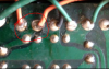
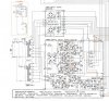
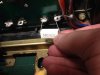
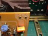
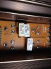
Hello Rottalpha, thank you very much for your input. Yes, I do have questions. Please see photos attached (sorry for poor quality). First, one of the over-hauled and calibrated, driver units. Then a picture of the driver board. So, without the driver board unit fitted, one attaches the probes to one of the green wires and then the orange wires to adjust? But, which is 'E', or earth? Would that be 'GR', (ground)?
Can I presume that 'Step 1' in the manual (100V) is done after 'Step 2' (+85V / -85V) and then fitting the driver boards.
Soory to ask what may be straight forward to you but, as my picture implies, I'm "not to swift to behold".View attachment 1469833View attachment 1469834View attachment 1469835

hold off with doing anything to that amp until you fully understand all the steps required to put it back together!

I will second @Vint Age that this is probably one of the worse apms to lose your cherry with. Very easy to mess it up...just as the tech you first took it to did.


For starters:

there is no 100v adjustment anywhere in this amp. I do not have the manual in front of me, but IIRC, the only mention of 100v is for the Japan models mains / transformer primaries. If you are in UK, you should make sure your amp is rated for ~230v or whatever mains you have there. If not use a step-down transformer.

IIRC< you have the regulated +/-85 v adjustment
Idle curent (bias) adjustment
DC offset.

+ the meter adjustments at the end....


Also, I see a bunch of corroded wires in your photo of the PSU. All of those wires need to be trimmed cleaned and soldered, after you also removed all of the old solder.


"E" is one of the many black wires in that PSU, but you are not ready for that yet.

my honest personal opinion is that you absolutely need to exhaust every possibility before you undertake this reassembly yourself. If your door to France is now closed,
there are a couple of very expereinced rebuilders, one in Holland and the other in Croatia. However, I am certain that you should be able to find a capable tech on your side of the pond.
 
Hello
The door to France is not closed but I am very disapointed by the fact to ask help to AK community . I offer my help and I read messages who make me understand that you are not able to re-connect something you have yourself disconnected.
I have taken the time to call you and explain you what you have to do (like to adjust the +85V and - 85V , that's all !)
you request info from members .......I Don't understand this behaviour
I can send movies with each heatsink working prefectly well in my own B2 . I am worried by the fact that you can damage all the job I have done and will be lost for ever. I don't see what is complicate to do to make your B2 working back
Both drivers boards are new all TR perfect and checked with curve tracer (one afternoon spend for each driver board) both heatsink get 4 V-FET perfectly working too
All of this for 2 hours labor only ! next time I get request like yours , I will ask for the unit complete
I hope that the four V-FET I supplied to you will not be wasted !
Last "detail" don't separate driver boards and heatsinks because they have been adjusted and don't need to touched in any way !
 
upload_2019-4-5_18-40-18.png

I actually believe it is good he posted photos and asked questions. His unit is definrely not ready to receive those v-fet assemblies. I would have sent out the entire unit for repair if mine looked like this.

Someone qualified needs to do some prep work on the PSU before reintroduceing the two amplifier assemblies....

that orange +85 supply wire is on its last legs. What happens if the bias to those vfets is intrerupted while B-2 is on duty?
I would not be surprized if the corroded wireing in this unit was not part of why the first set of problems arrose.

was the PSU recapped?
 
will be curious to see soldering of the 4 new capacitor "gold tune" on the power board . I tried to see on pictures but it is not very clear

why is that wire scorched like that??? ...and what else is in this shape around that PSU?? I don't know I just receive the two driver boards with heatsinks , that's all ....
 
don't know I just receive the two driver boards with heatsinks , that's all ...
exactly, so no one qualified was able to see other potential issues. I only spoted a couple but there might be more...so that is where I come from saying that the entire unit needs a go-over , before more v-fets are sent to v-fet heaven.
 
Hi David - Do you recall which fuse(s) blew when you had your first B-2 bad luck?

Also, did you notice any capacitor juice on the PCB when you changed out the main caps¿
 
Clinique Audio (B-2 expert) phoned me yesterday and described, at some length, how to calibrate the power supply output, without fitting the driver boards. Also, I now have the correct meter probes and am waiting delivery of a suitable resistor for discharging the power caps. Gosh! Learning a lot.
 
Clinique Audio phoned me Friday and described how to calibrate the power supply output, without fitting the drive boards. Also, I now have the correct meter probes and got suitable resistors for discharging the power caps. Gosh! Learning a lot.
 
Forgot to mention had cut small hole in the panel behind power caps to re-route the three wires that were in the way of the new power caps.
 

Attachments

  • IMG_1822.jpg
    IMG_1822.jpg
    73.1 KB · Views: 24
Here are a couple of replaced trans (I mean VFET's). I see they have an 'A' added in the name. Does this matter?IMG_1826.jpg
 
Last edited:
Back
Top Bottom