


You are using an out of date browser. It may not display this or other websites correctly.
You should upgrade or use an alternative browser.
You should upgrade or use an alternative browser.
B2
- Thread starter brinsmead
- Start date
David Litman
Active Member
Switched amp on. No puff of smoke, bangs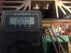
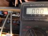 or sizzling. Phew! Meter set to AC. Did not touch either VR102's and reading is zero on both sides. I think thats meant to be good?
or sizzling. Phew! Meter set to AC. Did not touch either VR102's and reading is zero on both sides. I think thats meant to be good?
David Litman
Active Member
Couldn't resist pic of pretty new led's.

Some might argue that the A's are the better parts ...I see they have an 'A' added in the name. Does this matter?
Couldn't resist pic of pretty new led's.
Yours must be a silver faced B-2?
David Litman
Active Member
Hi David - Do you recall which fuse(s) blew when you had your first B-2 bad luck?
Also, did you notice any capacitor juice on the PCB when you changed out the main caps¿
Apologies I had missed some of your comments. No fuses had blown. I just had a hum in one channel. All caps on the power board have been replaced by my man in Glasgow. In his defence, I must say he did a fantastic job refreshing my Meridian 105's. Maybe, VFET's were a step too far. The scorched wire is my clumsy soldering, re-connecting and re-soldering all the wires to the power board. It had gone up and down many times in fitting the new large power caps and broken some of them. I am confident that although not pretty, my solder connections for the power caps are full and sound. That dodgy orange +85 solder refreshed as is any other poor looking connection.
Anyway, lets all calm down. I confess I was a little worried if I would see those parts again (the story privately confided with MiamiBoy) but, Clinique Audio has been very supportive now that I have the amp back. He has left the door open for me to call whenever I'm I am stuck, after hours. I can't ask for more than that.
Thank you to all you guys for your input. As I intimated before, I am learning a lot and have so much more to learn. I know almost nothing about electronics but, know a good quality sound system when I hear it. My mates call me a Hifi Snob.
Thanks for the clarification re step 1 in service manual (Japanese market). I guess I can now ignore that one.
So, power supply voltage, spot bollock (sorry, I mean 'on'). Also, I have done (as pictured below), supplied by very kind MiamiBoy. Please see pics above.
View attachment 1474150
Now, I'm stuck on this;View attachment 1474173
I only see NS and CT on each driver board. No + or -. Does it mean connect NS on one board and then the CT on the other board? Er. . . .?
Last edited:
David Litman
Active Member
Nice to know!Some might argue that the A's are the better parts ...
Yours must be a silver faced B-2?
David Litman
Active Member
Yes, silver face with the white VU's.Nice to know!

clinic-audio
all on YAMAHA untill 1990
David
Does your speakers relay's click ?
What are your measuring with your meter where I told you "do not touch anything , bias voltages and offset are already been adjusted ?? "
You are on AC
You should mesure DC Volt there !
I hope that you don't touch any adjustment .....On the both driver boards
Does your speakers relay's click ?
What are your measuring with your meter where I told you "do not touch anything , bias voltages and offset are already been adjusted ?? "
You are on AC
You should mesure DC Volt there !
I hope that you don't touch any adjustment .....On the both driver boards

MiamiBoy
Active Member
Now, I'm stuck on this;
I only see NS and CT on each driver board. No + or -. Does it mean connect NS on one board and then the CT on the other board? Er. . . .?
David, if you look closely at the original adjustment instructions in the service manual it shows a multi-meter's + and - leads connected to specific test points (NS, E or CT). The + or - is not printed on the board. And you definitely are connected to the SAME board not across boards. Go back and review the service manual's steps.
David Litman
Active Member
David
Does your speakers relay's click ?
What are your measuring with your meter where I told you "do not touch anything , bias voltages and offset are already been adjusted ?? "
You are on AC
You should mesure DC Volt there !
I hope that you don't touch any adjustment .....On the both driver boards
Yes, the relays definitely click. I have not adjusted anything except the power supply voltage which was measured in DC. They were hardly 0.3V out. Please see in the picture posted 3.25pm today, one probe on earth and one on the orange wire from +85V on the power board. I did not show pic for the green wire connection to calibrate the -85V.
I think you said that once power supply voltage was set (looks good to me, see pics above), I should check bias and dc balance on driver board, although they should be good to go thanks to your calibration?
I followed this instruction (below and above) but did not turn VR102 (bias pots) counter clockwise.
This is a far as I have got and picture showing results, above.
Last edited:
David Litman
Active Member
David, if you look closely at the original adjustment instructions in the service manual it shows a multi-meter's + and - leads connected to specific test points (NS, E or CT). The + or - is not printed on the board. And you definitely are connected to the SAME board not across boards. Go back and review the service manual's steps.
I thought so. Your instruction step 3 says "Bias left and right both sides". It also says "connect to the two drive boards". Confusing for dummy like me.
So, as in step 1 of your instructions, the probes are connect to NS and CT of one of the driver boards and the the bias pot is tweaked to get 40mV (0.04V) on the meter which is set to read AC? Is this right, please?
Now, by the way, I won't attempt this until I get an opinion from Clinique Audio. As you see above, he says don't touch anything (bar the telephone conversation instructing me how to set power output voltage)
Last edited:
David Litman
Active Member
I do, thank you. Although, its a bit fuzzy being a poor scan of the original. Heres a screen shot of a bit of it.David, you do have a copy of the service manual?

Last edited:
clinic-audio
all on YAMAHA untill 1990
David
Yes , don't touch anything
As I said by phone just check the bias voltage
you should read 40mV after 30 minutes between NS and CT (don't care about positive and negative probe)
Regarding offset you should read 0V between CT and E
All these values are in DC Volt nothing else
You don't need to read or follow any other instruction
Yes , don't touch anything
As I said by phone just check the bias voltage
you should read 40mV after 30 minutes between NS and CT (don't care about positive and negative probe)
Regarding offset you should read 0V between CT and E
All these values are in DC Volt nothing else
You don't need to read or follow any other instruction
David Litman
Active Member
Ok, meter set to DC connected to NS and CT of right driver board, settled down to 38.3mV.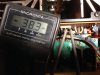
Meter set to DC connected to NS and CT of left driver board, settled down to 32.8mV.
Correction; left channel settled to 34.1mV
Meter set to DC connected to NS and CT of left driver board, settled down to 32.8mV.
Correction; left channel settled to 34.1mV
Last edited:
clinic-audio
all on YAMAHA untill 1990
Good
Don't touch anything
and what about offset ?
Don't touch anything
and what about offset ?
David Litman
Active Member
Ok, the Offset, driver board terminals CT and E, right. Around 17.7mV.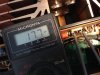 .
.
Driver board left. About 25.4mV.

And now. . . .?
.Driver board left. About 25.4mV.
And now. . . .?
clinic-audio
all on YAMAHA untill 1990
These values are not good
You should read 0V
I honestly don't understand how the both sides can move this way ....Are you sure about your meter ?
I will call you to tell you what to do and how to do it
PATRICE
You should read 0V
I honestly don't understand how the both sides can move this way ....Are you sure about your meter ?
I will call you to tell you what to do and how to do it
PATRICE
David Litman
Active Member
Not really sure about the meter. I've had it 20 or more years. Use it mainly to test batteries. It will measure a new "Industrial Duracell 1.5V battery at 1.596V which I fancy is probably about right. Happy to buy a new one to go with the new probes I got. They don't fit the sockets on the meter so they are connected to the old probes with crocodile clips. See picture. 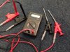
Can you recommend one from Amazon, please?
Can you recommend one from Amazon, please?
Last edited:
clinic-audio
all on YAMAHA untill 1990
David
Don't waste your money
Just use this one
Clips your BLACK probe to E
Clips your RED probe to CT
Adjust VR 101 to get 0V +- 10 mV
Double check after 30 minutes
Do the same on the other channel
Don't waste your money
Just use this one
Clips your BLACK probe to E
Clips your RED probe to CT
Adjust VR 101 to get 0V +- 10 mV
Double check after 30 minutes
Do the same on the other channel