Sam08861
Super Member
I've decided to give this a try, follow the example here, although with different amps. Don't have much experience in speaker building, bi-amping or using crossovers, so have some newbie questions.
https://www.audiophilenirvana.com/a...ws/altec-lansing-model-14-part-4-ultimate-14/
Components I'll be using:
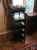
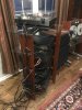
Technics SU-9070 Preamp (and source selector/phono stage) (+ RTR, CD, Streaming and Turntable as sources)
Luxman R-115 (amp section only to drive L/R Horns - Highs)
Luxman R-117 (amp section only to drive L/R Woofers - Mids)
Velodyne Optimum 8 Sub (Powered servo sub - Lows)
As far as parts needed to accomplish this:
2 47uf 250V Dayton Polypropylene Capacitors (to be place inline with the horns)
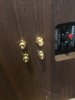
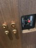
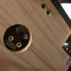
8 binding posts (existing posts will stay in place, but be disconnected, along with the internal crossovers)
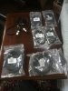
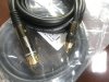
6 XLR Female to RCA Male Cables (Output L/R Pairs for H/M/L, 3',3' and 10')
1 XLR Male/Female Cable (for RTA Mic)
2 XLR Male to RCA Male Cables (Preamp, being used as a source selector to Crossover)
In addition, for the Active Crossover, I've obtained a Driverack PA2 and RTA microphone.
Costs are as follows: Binding Posts and Caps ~$70USD (tell me about it)
XLR Cables (16 GA Monoprice premium, ~$60)
Driverack PA2 & Microphone (Used, but never used) ~$370 shipped
----for a total of----> $500
This will take about 3-4 hours for me, since i'm OCD and cautious, to do the following:
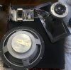
1. Remove Woofers, Horn, Crossovers and all internal Wiring
2. Tap in High and Mid Binding Post Pairs (parts express)
3. Solder Wire to Binding Posts, Solder and strap down Capacitors and add spade connectors for speakers
4. Reinstall Woofers, Horn and Crossover with new High and Low Connectors
5. Run Cabling from Preamp to Crossover
6. Run Cabling from Crossover to amps and powered subwoofer
7. Run Speaker wire from Amps to H/M/L Drivers as appropriate
8. Configure and Dial in the PA2.
Some questions:
1. I am assuming the Technics SU-70 is at -10db output, being a consumer model? (as opposed to pro/PA gear, which is at +4db) Just making sure since it's rack mounted and marketed as 'professional'
Specs are here and I can't quite make out how to figure this out... https://www.hifiengine.com/manual_library/technics/su-9070.shtml
2. In looking at the Driverack PA2, it has a facility to limit the output to the amplifiers and is in dBu units. Any suggestions on how to determine the max dBu at the inputs for each of the 3 amplifiers?
(as the 2 receivers do not have gain controls and clipping indicators as a professional amplifier would, I cannot use the procedure outlined in the setup procedure.
The sub has a gain control, but no clipping indicator)
The Driverack can output up to +20db. From reading I am thinking to set the threshold at -16db with a soft knee as a starting point?
Any suggestions on how the various amplifiers' input thresholds can be determined? Is there a suggested maximum dBu for consumer line level inputs I could use as a safe starting point? Can the gain be calculated from published specifications?
Will be glad to post the published specifications and reviews of the 3 amps in questions.
3. Assuming the capacitor should be place in line between the + input of the horn and the + binding post? (or does this matter since polarity is always reversing to move the voice coils?, or does this need to bridge the input terminals?)
The remainder of the setup seems straightforward so far, but I am hoping to figure these things out.
So far, I've received the PA2 unit and RTA Microphone and had on hand already the XLR cables to run from the preamp to the crossover. Binding Posts/Caps should be here Saturday and the remaining XLR cables next Wednesday.
Will post the how to pics and thoughts on if this ends up being worthwhile if anyone's interested.
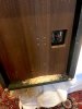
Save 4 1/4" holes for the binding posts, all else will be modified in a way as to be completely reversible. The binding posts I am thinking to mount on the bottom as well to keep the veneered surface intact. (since these speakers are veneered everywhere except the bottom and the small strip of Altec's special MDF between the horn and woofer boxes. (and insides, of course!)
https://www.audiophilenirvana.com/a...ws/altec-lansing-model-14-part-4-ultimate-14/
Components I'll be using:
Technics SU-9070 Preamp (and source selector/phono stage) (+ RTR, CD, Streaming and Turntable as sources)
Luxman R-115 (amp section only to drive L/R Horns - Highs)
Luxman R-117 (amp section only to drive L/R Woofers - Mids)
Velodyne Optimum 8 Sub (Powered servo sub - Lows)
As far as parts needed to accomplish this:
2 47uf 250V Dayton Polypropylene Capacitors (to be place inline with the horns)
8 binding posts (existing posts will stay in place, but be disconnected, along with the internal crossovers)
6 XLR Female to RCA Male Cables (Output L/R Pairs for H/M/L, 3',3' and 10')
1 XLR Male/Female Cable (for RTA Mic)
2 XLR Male to RCA Male Cables (Preamp, being used as a source selector to Crossover)
In addition, for the Active Crossover, I've obtained a Driverack PA2 and RTA microphone.
Costs are as follows: Binding Posts and Caps ~$70USD (tell me about it)
XLR Cables (16 GA Monoprice premium, ~$60)
Driverack PA2 & Microphone (Used, but never used) ~$370 shipped
----for a total of----> $500
This will take about 3-4 hours for me, since i'm OCD and cautious, to do the following:
1. Remove Woofers, Horn, Crossovers and all internal Wiring
2. Tap in High and Mid Binding Post Pairs (parts express)
3. Solder Wire to Binding Posts, Solder and strap down Capacitors and add spade connectors for speakers
4. Reinstall Woofers, Horn and Crossover with new High and Low Connectors
5. Run Cabling from Preamp to Crossover
6. Run Cabling from Crossover to amps and powered subwoofer
7. Run Speaker wire from Amps to H/M/L Drivers as appropriate
8. Configure and Dial in the PA2.
Some questions:
1. I am assuming the Technics SU-70 is at -10db output, being a consumer model? (as opposed to pro/PA gear, which is at +4db) Just making sure since it's rack mounted and marketed as 'professional'
Specs are here and I can't quite make out how to figure this out... https://www.hifiengine.com/manual_library/technics/su-9070.shtml
2. In looking at the Driverack PA2, it has a facility to limit the output to the amplifiers and is in dBu units. Any suggestions on how to determine the max dBu at the inputs for each of the 3 amplifiers?
(as the 2 receivers do not have gain controls and clipping indicators as a professional amplifier would, I cannot use the procedure outlined in the setup procedure.
The Driverack can output up to +20db. From reading I am thinking to set the threshold at -16db with a soft knee as a starting point?
Any suggestions on how the various amplifiers' input thresholds can be determined? Is there a suggested maximum dBu for consumer line level inputs I could use as a safe starting point? Can the gain be calculated from published specifications?
Will be glad to post the published specifications and reviews of the 3 amps in questions.
3. Assuming the capacitor should be place in line between the + input of the horn and the + binding post? (or does this matter since polarity is always reversing to move the voice coils?, or does this need to bridge the input terminals?)
The remainder of the setup seems straightforward so far, but I am hoping to figure these things out.
So far, I've received the PA2 unit and RTA Microphone and had on hand already the XLR cables to run from the preamp to the crossover. Binding Posts/Caps should be here Saturday and the remaining XLR cables next Wednesday.
Will post the how to pics and thoughts on if this ends up being worthwhile if anyone's interested.
Save 4 1/4" holes for the binding posts, all else will be modified in a way as to be completely reversible. The binding posts I am thinking to mount on the bottom as well to keep the veneered surface intact. (since these speakers are veneered everywhere except the bottom and the small strip of Altec's special MDF between the horn and woofer boxes. (and insides, of course!)