
• The move to the new server is done. There are some software and database maintenance updates in process. This has us passing the hat around to help out. We appreciate any donations. Seriously, even a dollar helps. The payment page may be found here - https://www.audiokarma.org/support.html

BOSE 601 Series ii crossover (only one Resistor and Capacitor in Xover )

Jpkwd

Active Member
hello Bose enthusiasts,
Anyone who rebuilt the Xover could indicate if this makes sense to them ?
Perhaps the Xover were modified, i have no way to know but am strating to suspect they might have been.

But maybe not, might be a leaner version of the network.
Eager to hear from anyone who has experience with these.

I am working on a pair of Bose 601 S2 and in the process of replacing crossover caps, i noticed the xover network was simpler than expected.

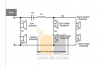
Much like this schematic, with only one C and one R
upload_2020-8-31_15-26-25.png

Caps probably didn't have to be replaced (film capacitors) but were not matched, and i thought i could change them anyways

So, noticed there was only one resistor and one Capacitor (which i thought of replacing with some Dayton audio caps i have around, hopefully of the right type :

https://solen.ca/products/capacitors/dayton-metallized-polypropylene-capacitors/dmpc-3-3/

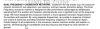
And reading this manual, the Xover parts list indicates way more components that my unique Cap and resistor.

http://www.umlib.com/brand/Bose/category/Speaker/model/601 Series II/document/135705

The first schematic is from this manual, and here is the description of the Xover network
upload_2020-8-31_15-21-33.png

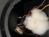
Here is a picture of the Xover in my 601'S (after replacement of the unique Cap in them)
upload_2020-8-31_15-23-13.png


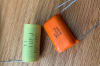
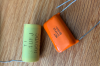
Here are the caps i removed (one in the left, and one in the right speaker, so each Xover had one cap - per speaker )
upload_2020-8-31_15-33-7.png

Here is a picture of a Xover looking a little bit like mine, and with similar caps
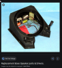
upload_2020-8-31_15-29-48.png

and some reference to another version of the xover found here on AK
https://audiokarma.org/forums/index.php?threads/bose-601-series-2-rebuild-questions.556484/page-2


upload_2020-8-31_15-32-12.png
 

Attachments

  • upload_2020-8-31_15-31-40.png
    upload_2020-8-31_15-31-40.png
    572.7 KB · Views: 30
  • upload_2020-8-31_15-32-2.png
    upload_2020-8-31_15-32-2.png
    572.7 KB · Views: 20
  • upload_2020-8-31_15-32-55.png
    upload_2020-8-31_15-32-55.png
    802 KB · Views: 20
Register to hide this ad
For the 2-terminal versions, there is only 1 cap and 1 resistor. The multiple listings of caps and resistors in the crossover table seems to be examples of what they used, but only one of each in each speaker. At least that appears to be the only way to reconcile the listing with the crossover diagram they provide in the same document, and is the way I interpreted it when I redid my crossovers.

However, I found a rather different complement of caps in my 601/IIs, and I bought them new from a retail stereo shop, in sealed original boxes, in 1987. My experience with what I found inside can be found here https://audiokarma.org/forums/index...series-ii-sansui-au9900.791610/#post-10932607
 
Thank you Northpaw,
i recalled having this discussion with you a while back. i did have in mind the comments you made back then when creating this thread.

i am still puzzled by this difference in crossovers.

so i have one 3.4uf, and one 3.9 ohms resistor per crossover

you have 7uf and 7.4uf, same resistance at 3.9 in both

wondering if there are other variants ?

why would we have different capacitance in our xover ?

it might be that at assembly some readings were made to adjust the crossover capacitance and resistance, but am not eve sure if this statement makes sense or not


perhaps some
 
I'm at a loss as to why there is as much variation in listed crossover capacitors, but I'm just baffled as to why my two units are so much higher in capacitance than the listed caps, or how a polar cap got in there. I could understand Bose fine tuning individual units, although I doubt they did so at the price point of these speakers, and it seems unlikely that the variations in their own drivers were that great. BTW, the resistors in my two are different: 3.9 in one, 5.1 in the other.
 
i wish i'd know more about speaker cross over designs. I read this type of design is the simplest and very effective.
Simple capacitor in series with the tweeters.

I mean, i've seen some simple equation for setting what the cut off frequency would be :

Cut off freq = 1/ (2 x Pi x Resistance x capacitance)

if that cut off needs to be fixed at a specific frequency, resistance and capacitance need to be adjusted.
Capacitance i get it is set with the caps.

Resistance for loads in series are accumulated (sum of all loads), perhaps that resistance in the cross over is used to set it to the right level.

To be honest, i do not master any of this. i wish i did, and if someone can explain it clearly i'll gladly incorporate this knowledge to my limited array of skills.
That may explain the variance we are looking at in each speakers.

I took a tweeter out (its a bit rotten, and i need to replace it). - makes me think i need to find a replacement one, and it is not easy. Advice welcome on where to find some aside from the site we can't name here (the big one).

So the reading was 5.5 ohms for the single speaker.

I've closed back the speakers, they sound right with the new cap so at least i haven't messed this up.
 
Hello. This is almost a year old now but thought I'd throw my 2 cents in.
I am far less knowledgable than you guys and found this thread looking to possibly recap my 601 series 2's. Bought mine used about 7 years ago at a great price as one 8" speaker was missing entirely and 2 of the the others needed new surrounds. (have gotten not half bad at replacing surrounds lol) When looking up specs to find a replacement Bose speaker for the missing one I found that the ohm rating on series 1-2-3 was not the same from series to series. It's been a while but as I recall the series 2 are 4 ohm.
Anyway Northpaw brought up the resistors were different from the right to the left. All of the classic Bose models I beleive were sold in rights and lefts (some obviously because of speaker placement) but the 601's and 901's were identical speaker placement.
So is the resistor difference intentional? One of probably many Amar(sp) secrets?
Cheers!
 
hello Bose enthusiasts,
Anyone who rebuilt the Xover could indicate if this makes sense to them ?
Perhaps the Xover were modified, i have no way to know but am strating to suspect they might have been.

But maybe not, might be a leaner version of the network.
Eager to hear from anyone who has experience with these.

I am working on a pair of Bose 601 S2 and in the process of replacing crossover caps, i noticed the xover network was simpler than expected.

Much like this schematic, with only one C and one R
View attachment 1968271

Caps probably didn't have to be replaced (film capacitors) but were not matched, and i thought i could change them anyways

So, noticed there was only one resistor and one Capacitor (which i thought of replacing with some Dayton audio caps i have around, hopefully of the right type :

https://solen.ca/products/capacitors/dayton-metallized-polypropylene-capacitors/dmpc-3-3/

And reading this manual, the Xover parts list indicates way more components that my unique Cap and resistor.

http://www.umlib.com/brand/Bose/category/Speaker/model/601 Series II/document/135705

The first schematic is from this manual, and here is the description of the Xover network

View attachment 1968268

Here is a picture of the Xover in my 601'S (after replacement of the unique Cap in them)

View attachment 1968269


Here are the caps i removed (one in the left, and one in the right speaker, so each Xover had one cap - per speaker )
View attachment 1968279

Here is a picture of a Xover looking a little bit like mine, and with similar caps

View attachment 1968272

and some reference to another version of the xover found here on AK
https://audiokarma.org/forums/index.php?threads/bose-601-series-2-rebuild-questions.556484/page-2
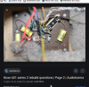
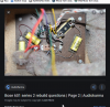
View attachment 1968275

You’re gonna love this story…20 some years ago I brought my speakers to guy in town to redo the foam on the woofers. Well since I can remember, the Left side symmetrical switch never worked while the Right side when moved back and forth an audible change is heard or a brighter tone. Well I finally decided to further investigate it and after looking at your crossover photo discovered the sob must have swapped out my capacitors with non polar nichicon type! I don’t have the yellow film and I can see where they were mounted by the foam still stuck the board,

The caps aren’t the reason for the problem though I did notice distortion. I ohm’ed the tweeters on the Left Side and all read about 7.9 ohms except for one that read 22.6 ohms. I’m in the process of replacing that one. I replaced the switch because it seemed be intermittent and ordering new metal film caps.

Here’s the weird part, I also checked the tweeters on the Right Side and they all read about 5.4 ohms! The manual says they are 8 ohm 3 inch tweeters so why the discrepancy? I’m concerned if I order a replacement and it too reads about 5.4 ohms and will that cause an impedance issue. Any thoughts?
 
You’re gonna love this story…20 some years ago I brought my speakers to guy in town to redo the foam on the woofers. Well since I can remember, the Left side symmetrical switch never worked while the Right side when moved back and forth an audible change is heard or a brighter tone. Well I finally decided to further investigate it and after looking at your crossover photo discovered the sob must have swapped out my capacitors with non polar nichicon type! I don’t have the yellow film and I can see where they were mounted by the foam still stuck the board,

The caps aren’t the reason for the problem though I did notice distortion. I ohm’ed the tweeters on the Left Side and all read about 7.9 ohms except for one that read 22.6 ohms. I’m in the process of replacing that one. I replaced the switch because it seemed be intermittent and ordering new metal film caps.

Here’s the weird part, I also checked the tweeters on the Right Side and they all read about 5.4 ohms! The manual says they are 8 ohm 3 inch tweeters so why the discrepancy? I’m concerned if I order a replacement and it too reads about 5.4 ohms and will that cause an impedance issue. Any thoughts?

Follow up….When measured in circuit, the 22.6 ohm Tweeter was actually open and when I installed a replacement, it read 7.6 out of the speaker close to the rest of the other tweeters on that speaker but dropped to 5.6 when installed, So now you know, if they are all reading around 5.6 ohms or so then you’re good,
 
Back
Top Bottom