• The move to the new server is done. There are some software and database maintenance updates in process. This has us passing the hat around to help out. We appreciate any donations. Seriously, even a dollar helps. The payment page may be found here - https://www.audiokarma.org/support.html

Building a poor mans variac (Dim Bulb Tester or DBT)

Is this type of DIY feature usefull?

  • Yes

    Votes: 21 100.0%
  • No

    Votes: 0 0.0%

  • Total voters
    21
  • Poll closed .
Sorry about that, got busy and clean forgot your question!

Pics comming up.

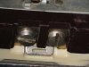
Here is the "bridge" in question. you stick in a screwdriver, and bend it back and forth,and it pops off separating the 2 duplex recepticals. Do this on the gold side ONLY for this application.

Ooo multiple pics in one post! :banana:

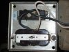
The second pic shows the wiring hookup.

Black (Hot) comes in from the GFIC and to one side of the switch, comes back out the other side and to the gold side you going to plug in the light socket adaptor. (you know a light socket with plug blades)

That forces the power through the bulb to the silver side, which is still bridged. Then the neutral (white) wire completes the circuit on the gold post that has load outlet. pick your bulb and volia! lower voltage :rockon:
 

Attachments

  • DB bridge.jpg
    DB bridge.jpg
    56 KB · Views: 684
  • DB wire.jpg
    DB wire.jpg
    89.5 KB · Views: 670
Last edited:
The PMV has an added bonus!

You may notice in those pictures I added in that 1st message that there is a heater strap connected to the Poor Mans Variac (PMV).

I discovered that with a 40 watt "drop" bulb in the PMV that my heater strap, which is used to keep my wine in the ideal range for fermentation, about 68-74F, it keeps the wine at exactly the right temp without all the unplugging/replugging I needed before because the strap alone can raise the temp to 80F or more!

Isn't it nice finding new ways to use existing DIY projects? :banana:

Paul
 
Be careful that the bulb gets hot - the cold resistance of a light bulb is much less than its hot or running resistance.
 
Gandalph said:
Be careful that the bulb gets hot - the cold resistance of a light bulb is much less than its hot or running resistance.

Yes, you're correct.

But (if you follow many of my threads you know there's always a 'but') :banana: because these devices are used as a crude current limiting device and not as a labratory quality variac we can tolerate a bit of slack :yes: . In reality, that first start-up with a 60 watt bulb (my usual chioce) still protects against massive in-rush current. You can actually see the immediate peak current as the bulb glows bright then dims after 1 or 2 seconds.

Yes, it's crude but it works and it only cost me $10. :thmbsp: And. it works!

Paul
 
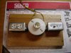
Now that mine is built after trial and error, I think it would have been much easier to use a extension cord and splice in a bulb socket and forget about the switch and recepticle.
What I do like about the recept is I can add an additional lamp to it and bring down the voltage farther.
 

Attachments

  • P5090001.JPG
    P5090001.JPG
    61.7 KB · Views: 536
Last edited:
No need for two bulbs. You can control the voltage drop with the wattage of the bulb. The smaller the wattage, the bigger the drop. You can start with, say, a 40 watt bulb and then 60 then 75 then 100.

- Pete
 
Stain, I'll add it to the improvement list for version 2.1. When you have a band saw, you just can't leave the corners of a board square. I should have hit it with the router and a round over bit to make it a little more finished.

On a different note, you can get yourself in trouble with these things. They will cause some protection circuits to kick in. A good protection circuit will activate if the operating voltage is too low and that is exactly what the lightbulb circuit does, drops the voltage. I've had it happen on a G-22000 and a 9090DB. Spent days trying to figure out why the G-22000 wouldn't come out of protection before I got brave and powered it up directly. I was smarter when it happened with the 9090DB.

Paul, this is a good thread by the way. Thanks for starting it.


Variacs (both regular and poor man's versions) should be used to power up TUBE (valve for the Brits) gear, NOT solid state! I'm reliably informed that you can actually damage some solid state components by running them on significantly lowered voltage. :nono:
 
To make life easier you can use a 3 way light bulb and socket so you don't have to switch bulbs to different wattages. You can use a 30/70/100 watt bulb or a higher wattage bulb depending on your load.

Regards,
Sal Brisindi
 
Variacs (both regular and poor man's versions) should be used to power up TUBE (valve for the Brits) gear, NOT solid state! I'm reliably informed that you can actually damage some solid state components by running them on significantly lowered voltage. :nono:

This may be true for some very esoteric SS gear but for most vintage gear (like a Sansui G-8000 or a 9090DB) this is safe. But, protection circuits may not come out of their 'quiet' state if the line voltage is too small. I generally use a 100 watt light bulb for 90% of my initial tests and that always (so far) allows the protection circuits to trigger. And as EchoWars recently pointed out (in another thread) these light bulb loads are terrific for setting the BIAS for a minimum draw on an initial start-up of an unknown amp -- a real clever step! :thmbsp:

Paul
 
I draw 83 volts with a 15 watt bulb, would'nt you want to start with a lower voltage than that for reforming caps?
 
Something is not right if you are getting 83v with a 15 watt bulb. You need to have something plugged in and operating to get a true reading.

- Pete
 
To make life easier you can use a 3 way light bulb and socket so you don't have to switch bulbs to different wattages. You can use a 30/70/100 watt bulb or a higher wattage bulb depending on your load.

Regards,
Sal Brisindi
That's a great idea in theory but I'm not sure those switches will handle the extra load of the gear you are testing for very long. They are not very heavy duty.

- Pete
 
Not true,
You will only draw the maximum current of the light bulb regardless of the load. If there was a dead short in the amp you were testing and you had the light set at 100 watts, guess what, only 100 watts of power would be used.

Regards,
Sal Brisindi
 
Somebody on AK suggested building a PMV this way and it really is a neat implementation of the idea, much handier than the 'cord / light / cord / socket' arrangement I'd been using. I used a computer power cord and a gray plastic 'old work' receptacle box for mine.
 
Here is what I got with a tube amp load:
Load Motorola Mono Tube amp, .62 @ 117VAC rating

bulb wattage - ohms resistance - resulting Voltage @121VAC
40 - 26 - 67
60 - 19 - 81
100 - 10 - 91
150 - 7.5 - 100
240 - 5 - 110

can anyone give me the (expected/approx) values for 220v? i have an idea or two bouncing around in my head but i'd need to know this before i start doing/building anything. thanks.
 
ManFromPorlock, I like the compactness of this design. I wired one up based on the advice of a friend and an earlier post but it isn't functioning right. Tried a couple receptacles.
If you don't mind, How did you wire yours.

With apologies for the lousy image; my digital cam doesn't do macro very well.

Now that I look at it, it seems as though I was a little more elaborate than I needed to be. I broke the brass tabs on both sides of the receptacle, then wired it as shown: one connection from the power cord to one side (call it side 'A') of one socket, a wire to connect side B of that socket to side A of the second socket, then a last connection from side B of the second socket back to the power cord.

For some reason I wanted the current flow across the two sockets to be in-phase rather than reversed-phase (well, it seemed like a good idea at the time), which is why the elaboration. But if one of the loads is just a lightbulb then breaking only one of the tabs and connecting the two power cord wires to the side the broken tab is on (one wire to each side of the break!) should do just as well.
 
My heart rate goes up about 20% everytime I plug the vom into an outlet as I've blown up more than one along with a few probes when I had it set to amps or ohms and forgot to reset it. :stupid:

Well its nice to see that I'm not alone in doing this.
 
Back
Top Bottom